WIRELESS DOOR LOCK CONTROL SYSTEM Door Control Receiver Circuit
DESCRIPTION
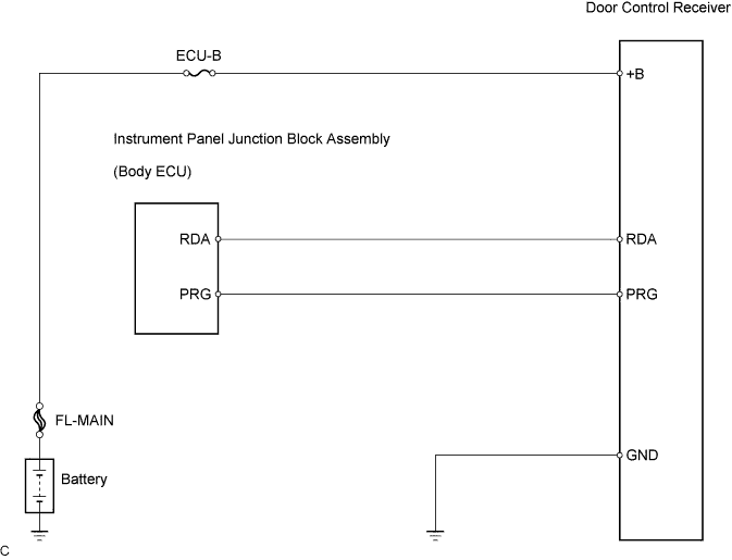
This door control receiver receives signals from the transmitter and sends these signals to the body ECU. The body ECU sends "LOCK" and "UNLOCK" signals to the door lock control motors.
WIRING DIAGRAM
INSPECTION PROCEDURE
PROCEDURE
-
INSPECT DOOR CONTROL RECEIVER (POWER SOURCE CIRCUIT)
-
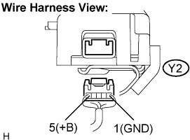
Disconnect the door control receiver connector.
-
Measure the voltage according to the value(s) in the table below.
Voltage Tester connection Condition Specified Condition Y2-1 (GND) - Y2-5 (+B) Always 10 to 14 V
NG 
CHECK HARNESS AND CONNECTOR (DOOR CONTROL RECEIVER - BODY GYOUND) Click here
OK 
-
-
CHECK HARNESS AND CONNECTOR (DOOR CONTROL RECEIVER - INSTRUMENT PANEL JUNCTION BLOCK)
-
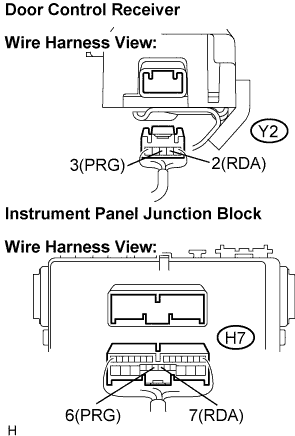
Disconnect the instrument panel junction block connector.
-
Measure the resistance according to the value(s) in the table below.
Resistance Tester connection Condition Specified Condition Y2-2 (RDA) - H7-7 (RDA) Always Below 1 Ω Y2-3 (PRG) - H7-6 (PRG) Always Below 1 Ω Y2-2 (RDA) - Body ground Always 10 kΩ or higher Y2-3 (PRG) - Body ground Always 10 kΩ or higher
NG 
REPAIR OR REPLACE HARNESS OR CONNECTOR
OK 
PROCEED TO NEXT CIRCUIT INSPECTION SHOWN IN PROBLEM SYMPTOMS TABLE
-
-
CHECK HARNESS AND CONNECTOR (DOOR CONTROL RECEIVER - BODY GYOUND)
-
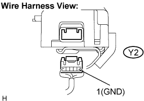
Measure the resistance according to the value(s) in the table below.
Resistance Tester connection Condition Specified Condition Y2-1 (GND) - Body ground Always Below 1 Ω
NG
REPAIR OR REPLACE HARNESS OR CONNECTOR
OK
REPAIR OR REPLACE HARNESS OR CONNECTOR (DOOR CONTROL RECEIVER - BATTERY)
-