POWER DOOR LOCK CONTROL SYSTEM Door Control Switch Circuit
DESCRIPTION
When a malfunction is detected in these switches, inspect each switch. Then, replace the malfunctioning switch. If no malfunction is detected in the switches, check the wire harness.
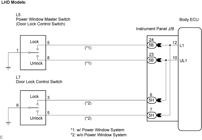
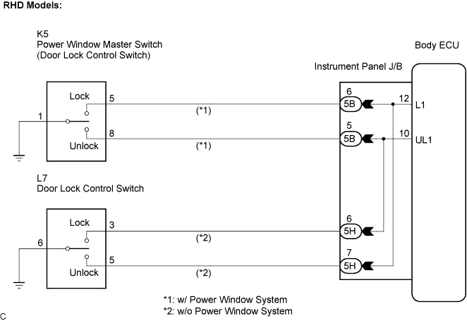
WIRING DIAGRAM
INSPECTION PROCEDURE
PROCEDURE
-
SYSTEM CIRCUIT CHECK
-
System circuit check
Door control circuit (w/ power window) A Door control circuit (w/o power window) B
B 
INSPECT DOOR CONTROL SWITCH ASSEMBLY Click here
A 
-
-
INSPECT POWER WINDOW MASTER SWITCH (DOOR CONTROL SWITCH)
-
Disconnect the power window master switch assembly.
-
Measure the resistance when the switch is operated according to the value(s) in the table below.
Standard resistance Tester Connection Door Lock Condition Specified Condition 1 - 8 ON (Door lock set to UNLOCK) Below 1 Ω 1 - 5 OFF (Door Lock set to LOCK) Below 1 Ω
NG 
REPLACE POWER WINDOW MASTER SWITCH
OK
-
-
CHECK WIRE HARNESS (POWER WINDOW MASTER SWITCH - INSTRUMENT PANEL J/B)
-
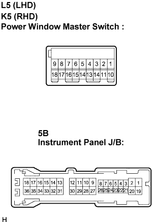
Disconnect the L5 (K5) connector.
-
Disconnect the instrument panel J/B connector.
-
Measure the resistance according to the value(s) in the table below.
Standard resistance LHD Models Tester Connection Condition Specified Condition 5B-23 - L5-8 (UL1) Always Below 1 Ω 5B-24 - L5-5 (L1) Always Below 1 Ω L5-1 - Body ground Always Below 1 Ω RHD Models Tester Connection Condition Specified Condition 5B-5 - K5-8 (UL1) Always Below 1 Ω 5B-6 - K5-5 (L1) Always Below 1 Ω K5-1 - Body ground Always Below 1 Ω
NG
REPAIR OR REPLACE HARNESS OR CONNECTOR
OK 
PROCEED TO NEXT CIRCUIT INSPECTION SHOWN IN PROBLEM SYMPTOMS TABLE
-
-
INSPECT DOOR CONTROL SWITCH ASSEMBLY
-
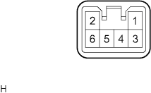
Disconnect the door control switch assembly.
-
Measure the resistance when the switch is operated according to the value(s) in the table below.
Standard resistance Tester Connection Condition Specified Condition 5 - 6 ON (Door lock set to UNLOCK) Below 1 Ω 3 - 6 OFF (Door Lock set to LOCK) Below 1 Ω
NG
REPLACE DOOR CONTROL SWITCH ASSEMBLY
OK
-
-
CHECK WIRE HARNESS (DOOR CONTROL SWITCH ASSEMBLY - INSTRUMENT PANEL J/B)
-
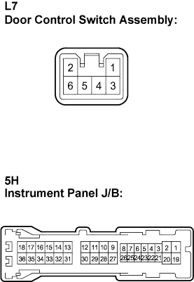
Disconnect the L7 connector.
-
Disconnect the instrument panel J/B connector.
-
Measure the resistance according to the value(s) in the table below.
Standard resistance Tester Connection Condition Specified Condition 5H-7 - L7-5 (L1) Always Below 1 Ω 5H-6 - L7-3 (UL1) Always Below 1 Ω L7-6 - Body ground Always Below 1 Ω
NG
REPAIR OR REPLACE HARNESS OR CONNECTOR
OK
PROCEED TO NEXT CIRCUIT INSPECTION SHOWN IN PROBLEM SYMPTOMS TABLE
-