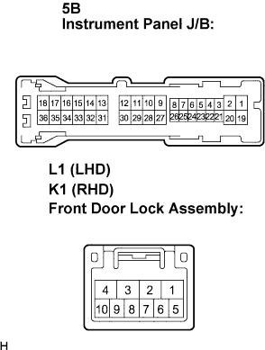
POWER DOOR LOCK CONTROL SYSTEM Driver Side Door Key Lock and Unlock Switch Circuit
DESCRIPTION
The door key lock and unlock switch is built in the door lock assembly.
This switch is turns on when the door key is in the unlock position and turns off when the door key is in the lock position. It is used as one of the operating conditions for the key confinement prevention function.
WIRING DIAGRAM
INSPECTION PROCEDURE
PROCEDURE
-
INSPECT FRONT DOOR LOCK ASSEMBLY (DOOR KEY LOCK AND UNLOCK SWITCH)
-
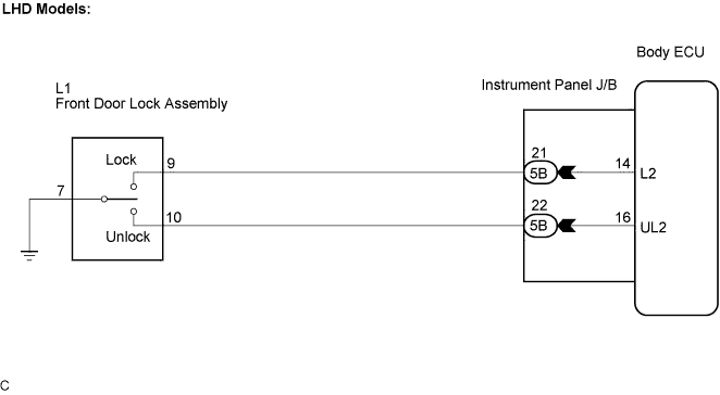
LHD Models:
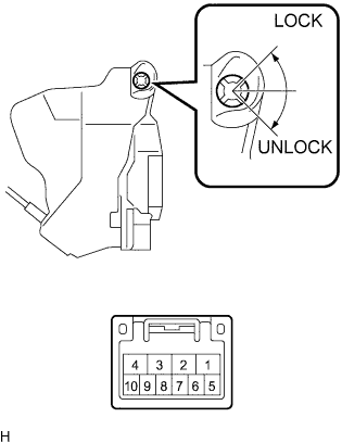
Inspect the front door lock assembly.
-
Measure the resistance when the switch is operated according to the value(s) in the table below.
Standard resistance Tester Connection Condition Specified Condition 10 - 7 ON (Door lock set to UNLOCK) Below 1 Ω 9 - 7 OFF (Door lock set to LOCK) Below 1 Ω
-
-
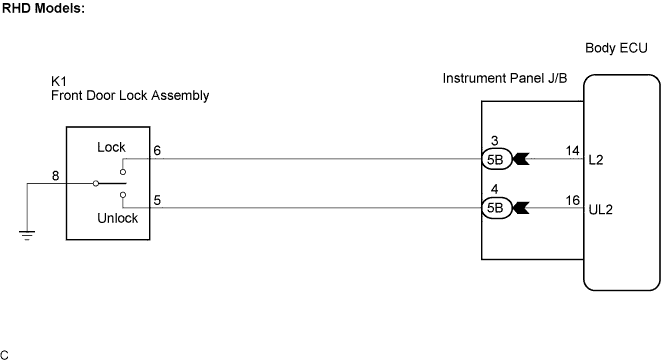
RHD Models:
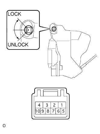
Inspect the front door lock assembly.
-
Measure the resistance when the switch is operated according to the value(s) in the table below.
Standard resistance Tester Connection Condition Specified Condition 5 - 8 ON (Door lock set to UNLOCK) Below 1 Ω 6 - 8 OFF (Door lock set to LOCK) Below 1 Ω
-
NG 
REPLACE FRONT DOOR LOCK ASSEMBLY
OK 
-
-
CHECK WIRE HARNESS (FRONT DOOR LOCK ASSEMBLY - INSTRUMENT PANEL J/B)
-
Disconnect the L1 (K1) connector.
-
Disconnect the instrument panel J/B connector.
-
Measure the resistance according to the value(s) in the table below.
Standard resistance LHD Models Tester Connection Condition Specified Condition 5B-21 - L1-9 Always Below 1 Ω 5B-22 - L1-10 Always Below 1 Ω L1-7 - Body ground Always Below 1 Ω RHD Models Tester Connection Condition Specified Condition 5B-3 - K1-6 Always Below 1 Ω 5B-4 - K1-5 Always Below 1 Ω K1-8 - Body ground Always Below 1 Ω
NG
REPAIR OR REPLACE HARNESS OR CONNECTOR
OK 
PROCEED TO NEXT CIRCUIT INSPECTION SHOWN IN PROBLEM SYMPTOMS TABLE
-