POWER DOOR LOCK CONTROL SYSTEM Slide Door Lock Motor RH Circuit
DESCRIPTION
The door lock motor is built in the door lock assembly.
The body ECU receives the rear left door lock switch signal from the master switch and operates the door lock motor.
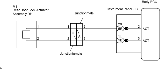
WIRING DIAGRAM
INSPECTION PROCEDURE
PROCEDURE
-
INSPECT REAR DOOR LOCK ACTUATOR ASSEMBLY RH
-
Inspect the slide door lock assembly RH.
-
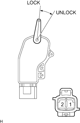
Apply battery voltage and check operation of the door lock motor.
Standard Measurement Condition Specified Condition Battery positive (+) → Terminal 1
Battery negative (-) → Terminal 2
Lock Battery positive (+) → Terminal 2
Battery negative (-) → Terminal 1
Unlock
NG 
REPLACE REAR DOOR LOCK ACTUATOR ASSEMBLY RH
OK 
-
-
INSPECT SLIDE DOOR CONTROL JUNCTIONFEMALE
-
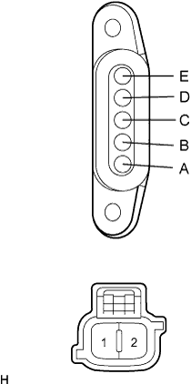
Inspect the slide door control junctionfemale.
-
Measure the resistance according to the value(s) in the table below.
Standard resistance Tester Connection Condition Specified Condition A - 1 Always Below 1 Ω E - 2 Always Below 1 Ω
NG
REPLACE SLIDE DOOR CONTROL JUNCTIONFEMALE
OK
-
-
INSPECT SLIDE DOOR CONTROL JUNCTIONMALE
-
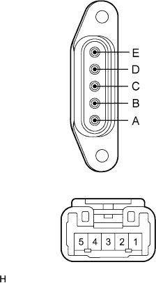
Inspect the slide door control junctionmale.
-
Measure the resistance according to the value(s) in the table below.
Standard resistance Tester Connection Condition Specified Condition A - 2 Always Below 1 Ω E - 3 Always Below 1 Ω
NG
REPLACE SLIDE DOOR CONTROL JUNCTIONMALE
OK
-
-
CHECK WIRE HARNESS (REAR DOOR LOCK ACTUATOR ASSEMBLY RH - INSTRUMENT PANEL J/B)
-
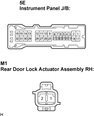
Disconnect the M1 connector.
-
Disconnect the instrument panel J/B connector.
-
Measure the resistance of the wire harness side connectors.
Standard resistance Tester Connection Condition Specified Condition 5E-26 - M1-1 (ACT+) Always Below 1 Ω 5E-11 - M1-2 (ACT-) Always Below 1 Ω
NG
REPAIR OR REPLACE HARNESS OR CONNECTOR
OK 
PROCEED TO NEXT CIRCUIT INSPECTION SHOWN IN PROBLEM SYMPTOMS TABLE
-