WIRELESS DOOR LOCK CONTROL SYSTEM (w/o Smart Entry and Start System) No Answer-back
DESCRIPTION
In some cases, wireless door lock control functions are normal but the hazard warning light answer-back function does not operate. In such cases, hazard warning light signal circuit may be malfunctioning.
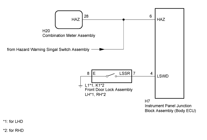
WIRING DIAGRAM
INSPECTION PROCEDURE
PROCEDURE
-
CHECK WIRELESS DOOR LOCK CONTROL FUNCTIONS
-
Check that the wireless door lock functions using the door control transmitter assembly Click here.
OK The wireless door lock functions using the door control transmitter assembly are normally.
NG 
GO TO OTHER FLOWCHART (Only Wireless Control Function is Inoperative) Click here
OK 
-
-
CHECK HAZARD WARNING LIGHTS
-
Check that the hazard warning lights blink when the hazard warning signal switch assembly is pressed.
OK Hazard warning lights flash continuously.
NG
GO TO LIGHTING SYSTEM Click here
OK
-
-
INSPECT FRONT DOOR LOCK ASSEMBLY (UNLOCK DETECTION SWITCH)
-
*1: for LHD
-
*2: for RHD
-
Remove the front door lock assembly LH*1 or RH*2 Click here
-
Inspect the front door lock assembly LH*1 or RH*2 Click here
NG
REPLACE FRONT DOOR LOCK ASSEMBLY Click here
OK
-
-
CHECK HARNESS AND CONNECTOR (INSTRUMENT PANEL JUNCTION BLOCK ASSEMBLY [BODY ECU] - FRONT DOOR LOCK ASSEMBLY AND BODY GROUND)
-
Disconnect the H7 instrument panel junction block assembly (body ECU) connector.
-
Disconnect the L1*1 or K1*2 front door lock assembly connector.
-
*1: for LHD
-
*2: for RHD
-
-
Measure the resistance according to the value(s) in the table below.
Standard Resistance for LHD Tester Connection Condition Specified Condition H7-4 (LSWD) - L1-7(LSSR) Always Below 1 Ω L1-8 (E) - Body ground Always Below 1 Ω H7-4 (LSWD) or L1-7(LSSR) - Body ground Always 10 kΩ or higher for RHD Tester Connection Condition Specified Condition H7-4 (LSWD) - K1-7(LSSR) Always Below 1 Ω K1-8 (E) - Body ground Always Below 1 Ω H7-4 (LSWD) or K1-7(LSSR) - Body ground Always 10 kΩ or higher
NG
REPAIR OR REPLACE HARNESS OR CONNECTOR
OK
-
-
CHECK HARNESS AND CONNECTOR (INSTRUMENT PANEL JUNCTION BLOCK ASSEMBLY [BODY ECU] - COMBINATION METER ASSEMBLY)
-
Disconnect the H7 instrument panel junction block assembly connector.
-
Disconnect the H20 combination meter assembly connector.
-
Measure the resistance according to the value(s) in the table below.
Standard Resistance Tester Connection Condition Specified Condition H7-6 (HAZ) - H20-26 (HAZ) Always Below 1 Ω H7-6 (HAZ) or H20-26 (HAZ) - Body ground Always 10 kΩ or higher
NG
REPAIR OR REPLACE HARNESS OR CONNECTOR
OK 
REPLACE INSTRUMENT PANEL JUNCTION BLOCK ASSEMBLY (BODY ECU)
-