WIPER SWITCH INSPECTION

-
INSPECT WIPER SWITCH (LHD)
-
Continuity Check
-
Measure the resistance according to the value(s) in the table below.
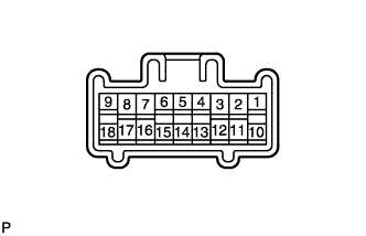
Resistance Front Wiper Switch Switch position Tester connection Specified condition MIST 17 (+B) - 7 (+1) Below 1 Ω OFF 16 (+S) - 7 (+1) Below 1 Ω INT 16 (+S) - 7 (+1) Below 1 Ω LO 17 (+B) - 7 (+1) Below 1 Ω HI 17 (+B) - 8 (+2) Below 1 Ω Front Washer Switch Switch position Tester connection Specified condition OFF 2 (E) - 11 (WF) 10 kΩ or higher ON 2 (E) - 11 (WF) Below 1 Ω Rear Wiper and Washer Switch Switch position Tester connection Specified condition WASH 2 (E) - 12 (WR) Below 1 Ω OFF 2 (E) - 13 (C1R)
2 (E) - 12 (WR)
2 (E) - 10 (+1R)
10 kΩ or higher INT 2 (E) - 13 (C1R) Below 1 Ω ON 2 (E) - 10 (+1R) Below 1 Ω ON + WASH 2 (E) - 12 (WR)
2 (E) - 10 (+1R)
Below 1 Ω If the result is not as specified, replace the wiper switch.
-
-
Intermittent Operation Check
-
Connect the voltmeter (+) terminal to terminal 7 (+1) and the voltmeter (-) terminal to terminal 2 (E).
-
Connect the battery's positive (+) lead to terminal 17 (+B), and connect the battery's negative (-) lead to terminals 2 (E) and 16 (+S).
-
Turn the wiper switch to the INT position.
-
Connect the battery's positive (+) lead to terminal 16 (+S) for 5 seconds.
-
Connect the battery's negative (-) lead to terminal 16 (+S) to operate the intermittent wiper relay. Measure the voltage between terminals 7 (+1) and 2 (E).
OK Refer to the illustration below. 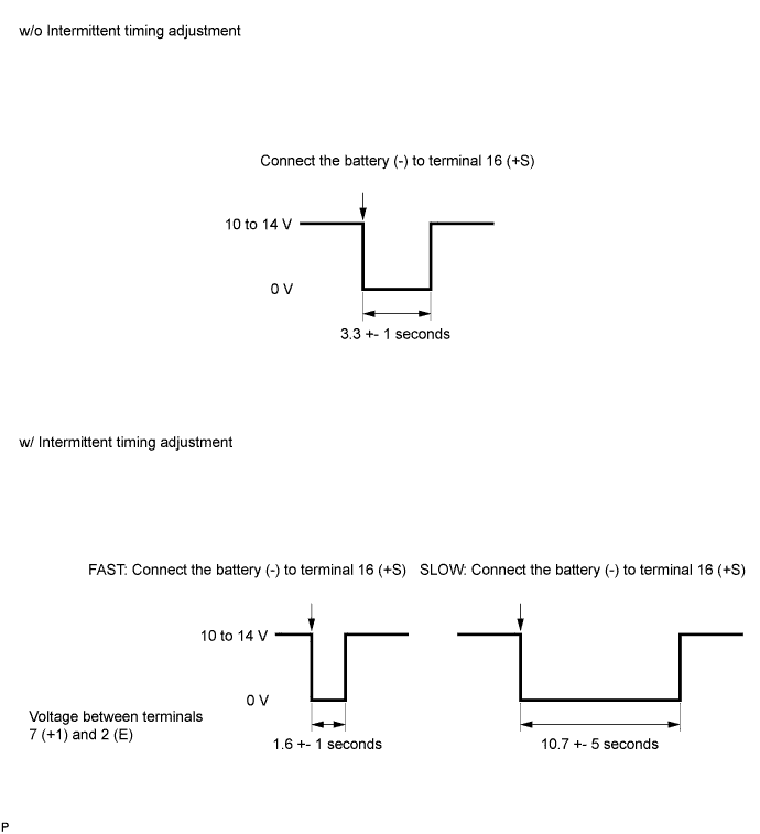
If the result is not as specified, replace the wiper switch.
-
-

Front Washer Operation Check
-
Turn the wiper switch to the OFF position.
-
Connect the battery's positive (+) lead to terminal 17 (+B), connect the battery's negative (-) to terminals 16 (+S) and 2 (E).
-
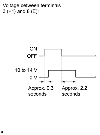
Connect the voltmeter (+) terminal to terminal 7 (+1) and the voltmeter (-) terminal to terminal 2 (E). Measure the voltage between terminals 7 (+1) and 2 (E) when turning the washer switch ON and OFF respectively.
OK Refer to the illustration. If the result is not as specified, replace the wiper switch.
-
-
-
INSPECT WIPER SWITCH (RHD)
-
Continuity Check
-
Measure the resistance according to the value(s) in the table below.
Resistance Front Wiper Switch Switch position Tester connection Specified condition MIST 11 (+B) - 3 (+1) Below 1 Ω OFF 12 (+S) - 3 (+1) Below 1 Ω INT 12 (+S) - 3 (+1) Below 1 Ω LO 11 (+B) - 3 (+1) Below 1 Ω HI 11 (+B) - 2 (+2) Below 1 Ω Front Washer Switch Switch position Tester connection Specified condition OFF 8 (E) - 17 (WF) 10 kΩ or higher ON 8 (E) - 17 (WF) Below 1 Ω Rear Wiper and Washer Switch Switch position Tester connection Specified condition Washer 8 (E) - 16 (WR) Below 1 Ω OFF 8 (E) - 15 (C1R)
8 (E) - 16 (WR)
8 (E) - 18 (+1R)
10 kΩ or higher INT 8 (E) - 15 (C1R) Below 1 Ω ON 8 (E) - 18 (+1R) Below 1 Ω On + Washer 8 (E) - 16 (WR)
8 (E) - 18 (+1R)
Below 1 Ω If result is not as specified, replace the wiper switch.
-
-
Intermittent Operation Check
-
Connect the voltmeter (+) terminal to terminal 3 (+1) and the voltmeter (-) terminal to terminal 8 (E).
-
Connect the battery's positive (+) lead to terminal 11 (+B), and connect the battery's negative (-) lead to terminals 8 (E) and 12 (+S).
-
Turn the wiper switch to the INT position.
-
Connect the battery's positive (+) lead to terminal 12 (+S) for 5 seconds.
-
Connect the battery's negative (-) lead to terminal 12 (+S) to operate the intermittent wiper relay. Measure the voltage between terminals 3 (+1) and 8 (E).
OK Refer to the illustration below. 
If the result is not as specified, replace the wiper switch.
-
-
Front Washer Operation Check
-
Turn the wiper switch to the OFF position.
-
Connect the battery's positive (+) lead to terminal 11 (+B), and connect the battery's negative (-) to terminals 12 (+S) and 8 (E).
-
Connect the voltmeter (+) terminal to terminal 3 (+) and the voltmeter (-) terminal to terminal 8 (E). Measure the voltage between terminals 3 (+1) and 8 (E) when turning the washer switch ON and OFF respectively.
OK Refer to the illustration. If the result is not as specified, replace the wiper switch.
-
-