AUTOMATIC LIGHT CONTROL SENSOR ON-VEHICLE INSPECTION

-
CHECK AUTOMATIC LIGHT CONTROL SENSOR (for LHD)
-
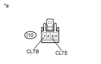
Text in Illustration *a Front view of wire harness connector
(to Automatic Light Control Sensor)
Disconnect the I10 automatic light control sensor connector.
-
Measure the voltage and resistance according to the value(s) in the table below.
Standard Voltage Tester Connection Switch Condition Specified Condition I10-1 (CLTB) - I10-3 (CLTE) Ignition switch off Below 1 V Ignition switch on (IG) 10 to 14 V Standard Resistance Tester Connection Condition Specified Condition I10-3 (CLTE) - Body ground Always Below 1 Ω If the result is not as specified, there may be a malfunction on the wire harness side.
-
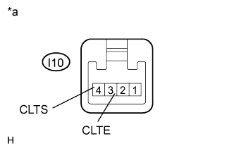
Text in Illustration *a Component with harness connected
(Automatic Light Control Sensor)
Reconnect the I10 automatic light control sensor connector.
-
Connect an oscilloscope to the automatic light control sensor connector.
-
Check the waveform.
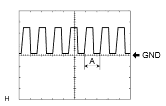
OK Tester Connection Tool Setting Switch Condition Specified Condition I10-3 (CLTE) - I10-4 (CLTS) 5 V/DIV., 5 ms./DIV Ignition switch on (IG), light control switch in AUTO position Correct waveform is as shown Tech Tips
If the ambient light becomes brighter, width A becomes narrower.
If the result is not as specified, the automatic light control sensor may have a malfunction.
-
-
CHECK AUTOMATIC LIGHT CONTROL SENSOR (for RHD)
-
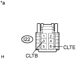
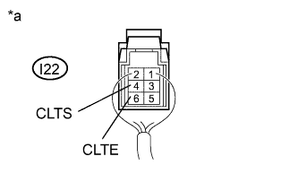
Text in Illustration *a Front view of wire harness connector
(to Automatic Light Control Sensor)
Disconnect the I22 automatic light control sensor connector.
-
Measure the voltage and resistance according to the value(s) in the table below.
Standard Voltage Tester Connection Switch Condition Specified Condition I22-3 (CLTB) - I22-6 (CLTE) Ignition switch off Below 1 V Ignition switch on (IG) 10 to 14 V Standard Resistance Tester Connection Condition Specified Condition I22-6 (CLTE) - Body ground Always Below 1 Ω If the result is not as specified, there may be a malfunction on the wire harness side.
-
Text in Illustration *a Component with harness connected
(Automatic Light Control Sensor)
Reconnect the I22 automatic light control sensor connector.
-
Connect an oscilloscope to the automatic light control sensor connector.
-
Check the waveform.
OK Tester Connection Tool Setting Switch Condition Specified Condition I22-6 (CLTE) - I22-4 (CLTS) 5 V/DIV., 5 ms./DIV Ignition switch on (IG), light control switch in AUTO position Correct waveform is as shown Tech Tips
If the ambient light becomes brighter, width A becomes narrower.
If the result is not as specified, the automatic light control sensor may have a malfunction.
-