INSTRUMENT PANEL SAFETY PAD INSTALLATION

-
INSTALL INSTRUMENT PANEL ASSEMBLY
-
Set the instrument panel assembly in place.
-
Install the 2 clips and 2 nuts <D> and 3 screws <B> and 4 bolts <A>.
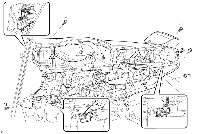
Text in Illustration *1 Bolt A *2 Screw B *1 Nut D - -
-
-
INSTALL FRONT PILLAR GARNISH RH
-
INSTALL FRONT PILLAR GARNISH LH
-
INSTALL ASSIST GRIP ASSEMBLY
-
INSTALL FRONT ASSIST GRIP PLUG NO. 1
-
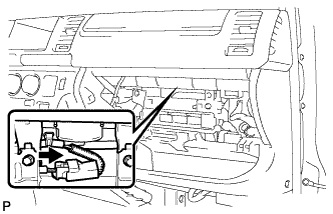
INSTALL HAZARD WARNING SIGNAL SWITCH ASSEMBLY
-
Connect the connector.
-
Attach the 2 claws to install the hazard warning signal switch.
-
-
INSTALL FRONT PASSENGER AIRBAG ASSEMBLY (w/ Front Passenger Airbag)
-
Engage the clamps and claws, and install the front passenger airbag assembly.
-
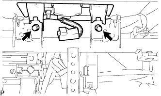
Install the instrument panel passenger airbag with the 2 bolts.
- Torque:
- 18 N*m { 184 kgf*cm, 13 ft.*lbf }
-
Connect the airbag connector.
-
Install the airbag connector to the reinforcement.
-
-
INSTALL GLOVE COMPARTMENT DOOR ASSEMBLY
-
Attach the 2 hinges to install the glove compartment door assembly.
-
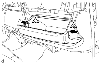
Push the positions indicated by the arrows in the illustration inward to attach the 2 stoppers.
-
-
INSTALL INSTRUMENT CLUSTER FINISH PANEL SUB-ASSEMBLY LOWER CENTER
-
w/ No. 3 Heater Control Knob
Attach the 2 claws to connect the air mix damper control cable sub-assembly to the No. 3 heater control knob.
-
Attach the 2 claws to connect the heater control cable sub-assembly to the heater control knob.
-
Attach the 2 claws to connect the air inlet damper control cable sub-assembly to the No. 2 heater control knob.
-
Connect the cable to the clamp.
-
Connect the connector.
-
Attach the 8 claws to install the instrument cluster finish panel sub-assembly lower center (air conditioning control assembly).
-
-
INSTALL SHIFT LOCK CONTROL UNIT ASSEMBLY (for Automatic Transmission)
For 1KD-FTV, 2KD-FTV Click here
For 1TR-FE Click here
For 2TR-FE Click here
-
INSTALL FLOOR SHIFT SHIFT LEVER ASSEMBLY (for Manual Transmission)
For 5L-E Click here
For 1KD-FTV, 2KD-FTV, 2TR-FE Click here
-
INSTALL INSTRUMENT PANEL FINISH PANEL LOWER CENTER
-
Attach the 8 claws to install the instrument panel finish panel lower center.
-
-
INSTALL SHIFTING HOLE COVER ASSEMBLY
-
for Manual Transmission:
Attach the 6 claws to install the shifting hole cover assembly.
-
for Automatic Transmission:
Attach the 8 claws to install the shifting hole cover assembly.
-
-
INSTALL SHIFT LEVER KNOB
-
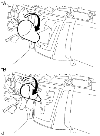
Text in Illustration *A for Manual Transmission *B for Automatic Transmission Turn the shift lever knob in the direction indicated by the arrow and install it.
-
-
INSTALL PARKING BRAKE HOLE COVER
-
Attach the 6 claws to install the parking brake hole cover.
-
-
INSTALL INSTRUMENT PANEL UNDER COVER SUB-ASSEMBLY NO. 1
-
Attach the 3 claws to instrument panel under cover sub-assembly No. 1.
-
Install the the 2 clips.
-
-
INSTALL INSTRUMENT PANEL FINISH PANEL LOWER
-
Connect the fuel lid lock control cable and bonnet (hood) control cable assembly to the instrument panel finish lower.
-
Attach the 4 clips to install the instrument panel finish panel lower.
-
Install the 2 clips.
-
-
INSTALL RADIO RECEIVER ASSEMBLY WITH BRACKET (w/ Radio Receiver)
-
INSTALL STEREO OPENING COVER WITH BRACKET (w/o Radio Receiver)
-
Install the stereo tuner opening cover with bracket with the 4 screws <C>.
-
-
INSTALL INSTRUMENT PANEL CUP HOLDER ASSEMBLY
-
Install the instrument panel cup holder assembly with the 3 screws <C>.
-
-
INSTALL COMBINATION METER ASSEMBLY
-
Attach the wire harness clamp and connect the 2 connectors.
-
Attach the 2 claws to install the combination meter assembly.
-
Install the 2 screws.
-
-
INSTALL INSTRUMENT CLUSTER FINISH PANEL SUB-ASSEMBLY
-
Attach the 6 claws and a hooks to install the instrument cluster finish panel sub-assembly.
-
-
INSTALL INSTRUMENT CLUSTER FINISH PANEL ASSEMBLY
-
Attach the 4 claws to install the instrument cluster finish panel assembly.
-
-
INSTALL INSTRUMENT CLUSTER FINISH PANEL GARNISH NO. 1
-
Attach the 3 claws to install the instrument cluster finish panel garnish No. 1.
-
-
INSTALL INSTRUMENT CLUSTER FINISH PANEL SUB-ASSEMBLY CENTER
-
for Standard Body:
Attach the 14 claws to install the instrument cluster finish panel sub-assembly center.
-
for Wide Body:
Attach the 16 claws to install the instrument cluster finish panel sub-assembly center.
-
-
INSTALL INSTRUMENT CLUSTER FINISH PANEL GARNISH NO. 2
-
Attach the 3 claws to install the instrument cluster finish panel garnish No. 2.
-
-
INSTALL TURN SIGNAL SWITCH WITH SPIRAL CABLE (w/ Airbag System)
-
Set the turn signal switch with spiral cable to the steering column.
-
While loosening the band clamp, attach the claw to install the turn signal switch with spiral cable.
-
Connect each connector.
-
-
INSTALL TURN SIGNAL SWITCH WITH WIPER SWITCH (w/o Airbag System)
-
Set the turn signal switch with wiper switch to the steering column.
-
While loosening the band clamp, attach the claw to install the turn signal switch with wiper switch.
-
Connect each connector.
-
-
INSTALL KEY CYLINDER LIGHT ASSEMBLY (w/ Key Cylinder Light)
-
Attach the claw to install the key cylinder light assembly.
-
-
INSTALL STEERING COLUMN COVER UPPER
-
Install the steering column cover upper.
-
-
INSTALL STEERING COLUMN COVER LOWER
-
Engage the 4 claws to install the steering column lower cover to the steering column upper cover.
-
Using a "TORX" socket wrench (T25), tighten the 2 screws.
-
-
INSTALL STEERING COLUMN COVER LOWER NO. 2 (w/ Smart Entry and Start System)
-
Install the 4 guide pins install the No. 2 steering column lower cover.
-
-
ADJUST SPIRAL CABLE SUB-ASSEMBLY (w/ Airbag System)
Note
Do not adjust the spiral cable with the battery connected and the ignition switch ON.
-
Check that the ignition switch is off.
-
Check that the cable is disconnected from the negative (-) battery terminal.
CAUTION:
Wait at least 90 seconds after disconnecting the cable from the negative (-) battery terminal to disable the SRS system.
-
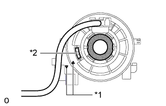
Text in Illustration *1 Alignment Mark *2 Flat Cable Check if the spiral cable sub-assembly is centered.
Tech Tips
When the spiral cable sub-assembly is centered, the alignment marks are aligned and the flat cable shown in the illustration is visible.
-
If the spiral cable sub-assembly is not centered, center it.
-
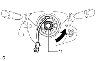
Text in Illustration *1 Interlock While pushing on the interlock indicated in the illustration, rotate the spiral cable sub-assembly counterclockwise slowly by hand until it stops.
Note
-
When rotating the spiral cable sub-assembly, make sure to push on the interlock indicated in the illustration to release the interlock mechanism.
-
Do not turn the spiral cable sub-assembly using the airbag wire harness.
-
-
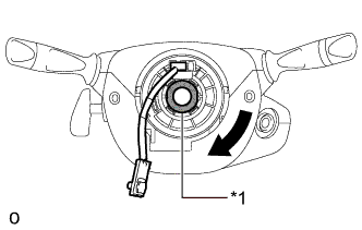
Text in Illustration *1 Interlock While pushing on the interlock indicated, rotate the spiral cable sub-assembly clockwise approximately 2.5 turns to the position where the flat cable is visible.
Note
-
When rotating the spiral cable sub-assembly, make sure to push on the interlock indicated in the illustration to release the interlock mechanism.
-
Do not turn the spiral cable sub-assembly using the airbag wire harness.
Tech Tips
The spiral cable will rotate approximately 2.5 turns to both the left and right from the center.
-
-
-
-
INSTALL STEERING WHEEL ASSEMBLY
-
Align the matchmarks on the steering wheel assembly and the steering column assembly.
-
Install the steering wheel set nut.
- Torque:
- 50 N*m { 510 kgf*cm, 37 ft.*lbf }
-
Connect the connectors.
-
-
INSTALL STEERING PAD (w/o Airbag System)
-
Connect the horn connector.
-
Using a "TORX" socket wrench (T30), tighten the 2 screws.
- Torque:
- 1.5 N*m { 15 kgf*cm, 13 in.*lbf }
-
-
INSTALL STEERING PAD (w/ Airbag System)
-
Check that the ignition switch is off.
-
Check that the cable is disconnected from the negative (-) battery terminal.
CAUTION:
Wait at least 90 seconds after disconnecting the cable from the negative (-) battery terminal to disable the SRS system.
-
Support the steering pad with one hand.
-
Connect the airbag connector to the steering pad.
Note
When connecting any airbag connector, take care not to damage the airbag wire harness.
-
Push in the airbag connector lock to connect the airbag connector.
-
Connect the horn connector to the steering pad.
-
Install the steering pad.
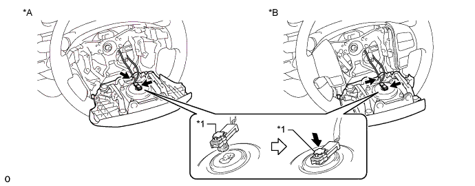
Text in Illustration *A w/o Steering Pad Switch *B w/ Steering Pad Switch *1 Connector Lock - - -
Using a T30 "TORX" socket wrench, tighten the 2 "TORX" screws.
- Torque:
- 8.8 N*m { 90 kgf*cm, 78 in.*lbf }
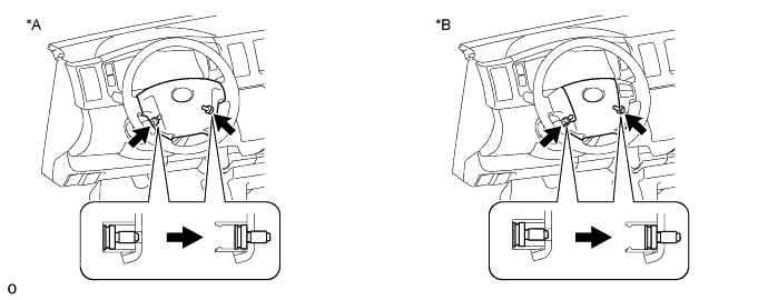
Text in Illustration *A w/o Steering Pad Switch *B w/ Steering Pad Switch
-
-
INSTALL STEERING WHEEL COVER LOWER NO. 3
-
INSTALL STEERING WHEEL COVER LOWER NO. 2
-
CONNECT CABLE TO NEGATIVE BATTERY TERMINAL
Note
When disconnecting the cable, some systems need to be initialized after the cable is reconnected Click here.
-
INSPECT STEERING PAD (w/ Airbag System)
-
With the steering pad installed on the vehicle, perform a visual check. If there are any defects as mentioned below, replace the steering pad with a new one:
Cuts, small cracks or marked discoloration on the steering pad top surface or in the grooved portion.
-
Make sure that the horn sounds.
Tech Tips
If the horn does not sound, inspect the horn system Click here.
-
-
INSPECT SRS WARNING LIGHT (w/ Airbag System)