INSTRUMENT PANEL SAFETY PAD REMOVAL

-
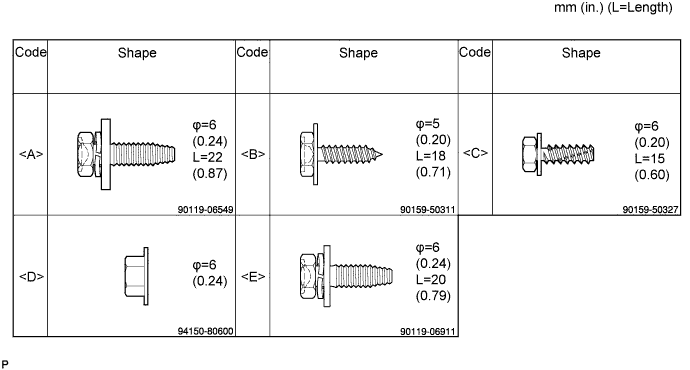
BOLT, SCREW AND NUT TABLE
Tech Tips
All bolts, screws and nuts relevant to installing and removing the instrument panel are shown along with their alphabet code in the table below.
-
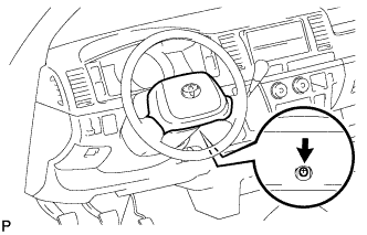
DISCONNECT CABLE FROM NEGATIVE BATTERY TERMINAL
CAUTION:
Wait for 90 seconds after disconnecting the cable to prevent the airbag working Click here.
Note
When disconnecting the cable, some systems need to be initialized after the cable is reconnected Click here.
-
REMOVE STEERING WHEEL NO.2 COVER LOWER
-
REMOVE STEERING WHEEL NO.3 COVER LOWER
-
REMOVE STEERING PAD (w/o SRS Airbag)
-
Remove the screw.
-
Remove the steering pad.
-
Disconnect the horn connector.
-
-
REMOVE STEERING PAD (w/ SRS Airbag)
-
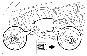
Using a "torx" socket wrench (T30), loosen the 2 "torx" screws until the groove along the screw circumference catches on the screw case.
-
Pull out the steering pad from the steering wheel assembly and support the steering pad with one hand.
-
Disconnect the horn connector.
-
Disconnect the connector and remove the steering pad.
Note
When handling the airbag connector, take care not to damage the airbag wire harness.
-
-
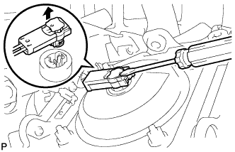
REMOVE STEERING WHEEL ASSEMBLY
-
Remove the steering wheel set nut.
-
Put matchmarks on the steering wheel assembly and steering main shaft assembly.
-
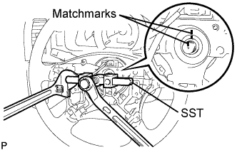
Using SST, remove the steering wheel assembly.
- SST
- 09950-50013 ( 09951-05010, 09952-05010, 09953-05020, 09954-05021 )
-
-
REMOVE STEERING COLUMN COVER LOWER
-
Set the steering tilt mechanism to the lowermost position.
-
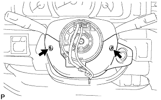
Remove the 2 "torx" screws from the steering column cover lower.
-
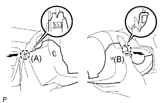
Press on the left side of the steering column cover lower to disengage claw A.
-
Press on the right side of the steering column cover lower to disengage claw B.
Tech Tips
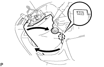
If it is difficult to disengage claw B, enlarge the clearance downward on the left side of the steering column cover lower to disengage the claw.
Twist the steering column cover lower by pulling it downward.
Note
Be sure to pull the steering column cover lower downward to prevent damage to the claw.
-
-
REMOVE KEY CYLINDER LIGHT ASSEMBLY (w/ Key Cylinder Light)
-
REMOVE STEERING COLUMN COVER UPPER
-
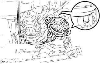
REMOVE HEADLIGHT DIMMER SWITCH ASSEMBLY
-
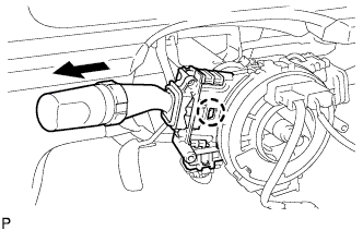
Disconnect the connector.
-
Disengage the claw and remove the headlight dimmer switch as shown in the illustration.
Note
If the claw is pushed with excessive force, it may break.
Tech Tips
Slide the steering column upper cover upward to remove the headlight dimmer switch.
-
-
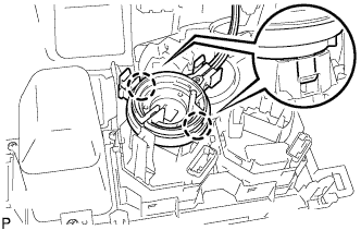
REMOVE WINDSHIELD WIPER SWITCH ASSEMBLY
-
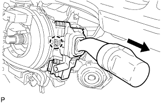
Disconnect the connector.
-
Disengage the claw and remove the wiper switch as shown in the illustration.
Note
If the claw is pushed with excessive force, it may be broken.
Tech Tips
Slide the steering column cover upper upward to remove the wiper switch.
-
-
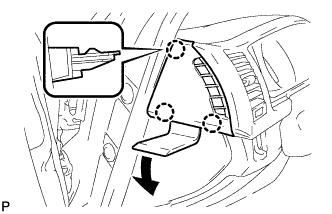
REMOVE INSTRUMENT CLUSTER FINISH PANEL NO.2 GARNISH
-
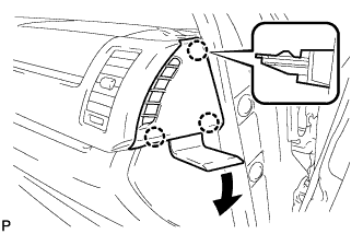
Using a moulding remover, disengage the 3 claws and remove the instrument cluster finish panel No.2 garnish.
-
-
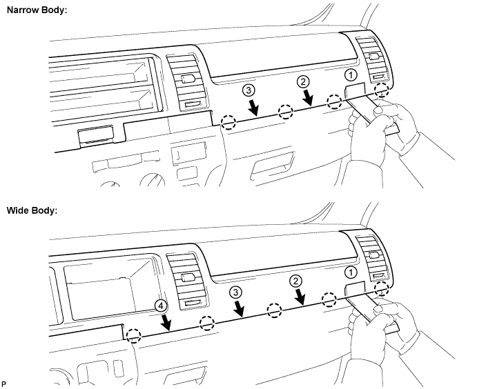
REMOVE INSTRUMENT CLUSTER FINISH PANEL SUB-ASSEMBLY CENTER
-
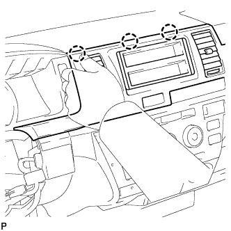
Using a roof moulding remover, disengage the claws in the order shown in the illustration.
-

Attach tape to the positions shown in the illustration in order to prevent the instrument cluster finish panel sub-assembly center from being damaged.
-
Using a moulding remover, disengage the claw.
-
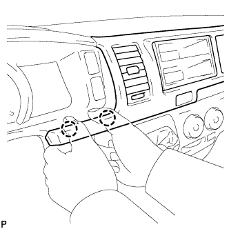
Hold the panel as shown in the illustration and pull it toward the rear of the vehicle to disengage the claws.
-
While supporting the panel with your right hand, pull it toward the rear of the vehicle to disengage the claws.
-
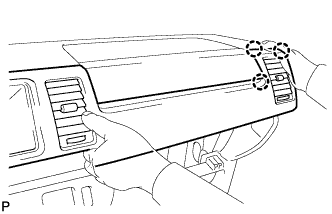
Hold the panel as shown in the illustration and disengage the claws.
-
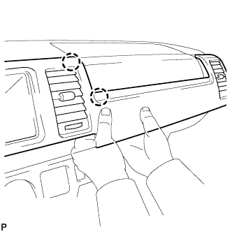
Hold the panel as shown in the illustration and pull it toward the rear of the vehicle to disengage the claws. Remove the instrument cluster finish panel sub-assembly center.
-
-
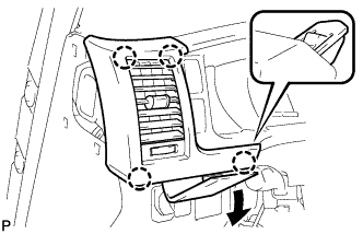
REMOVE INSTRUMENT CLUSTER FINISH PANEL NO.1 GARNISH
-
Using a moulding remover, disengage the 3 claws and remove the instrument cluster finish panel No.1 garnish.
-
-
REMOVE INSTRUMENT CLUSTER FINISH PANEL ASSEMBLY
-
Using a moulding remover, disengage the 4 claws and remove the instrument cluster finish panel assembly.
-
-
REMOVE INSTRUMENT CLUSTER FINISH PANEL SUB-ASSEMBLY
-
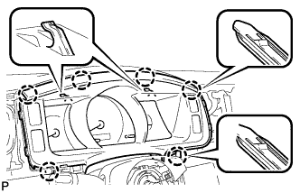
Disengage the 6 claws and remove the instrument cluster finish panel sub-assembly.
-
-
REMOVE COMBINATION METER ASSEMBLY
-
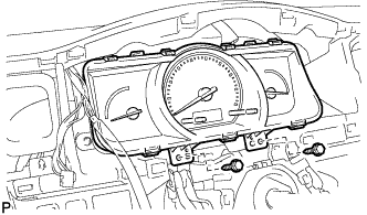
Remove the 2 screws <B>.
-
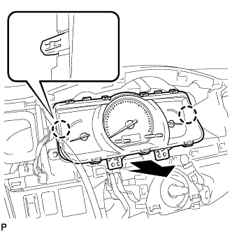
Disengage the 2 claws.
-
Disconnect the connector and remove the combination meter assembly.
-
-
REMOVE INSTRUMENT PANEL CUP HOLDER ASSEMBLY
-
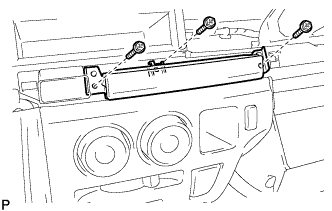
Remove the 3 screws <C> and the instrument panel cup holder assembly.
-
-
REMOVE STEREO OPENING COVER WITH BRACKET
-
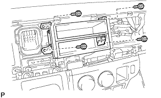
Remove the 4 screws <C> and the stereo opening cover with bracket.
-
-
REMOVE RADIO RECEIVER ASSEMBLY WITH BRACKET
-
Remove the 4 screws.
-
Disconnect the connectors and the radio receiver assembly with bracket.
-
-
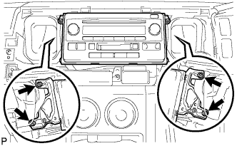
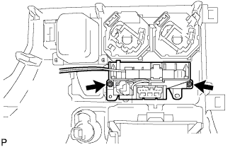
REMOVE INSTRUMENT PANEL FINISH PANEL LOWER
-
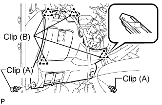
Using a clip remover, remove the 2 clips (A).
-
Disengage the 4 clips (B).
-
Disconnect the connector.
-
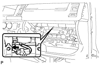
Push the positions indicated by the arrows in the illustration to separate the fuel lid lock control cable and bonnet (hood) control cable assembly from the panel.
Remove the instrument panel finish lower.
-
-
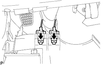
REMOVE INSTRUMENT PANEL NO.1 UNDER COVER SUB-ASSEMBLY
-
Using a clip remover, remove the 2 clips
-
Disengage the 3 claws and remove the instrument panel No.1 under cover sub-assembly.
-
-
REMOVE PARKING BRAKE HOLE COVER
-
Disengage the 6 claws and remove the parking brake hole cover.
-
-
REMOVE SHIFT LEVER KNOB
-
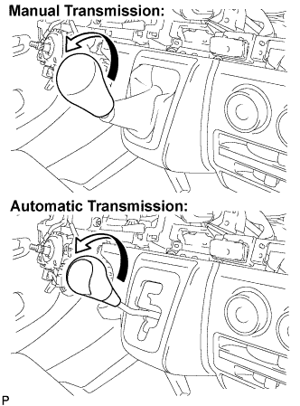
Turn the shift lever knob in the direction indicated by the arrow and remove it.
-
-
REMOVE SHIFTING HOLE COVER ASSEMBLY
-
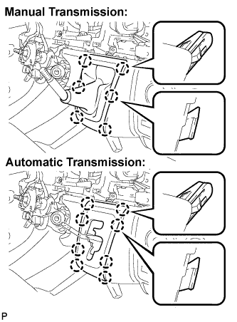
Manual Transmission:
Disengage the 6 claws and remove the shifting hole cover assembly.
-
Automatic Transmission:
Disengage the 8 claws and remove the shifting hole cover assembly.
-
-
REMOVE INSTRUMENT PANEL FINISH PANEL LOWER CENTER
-
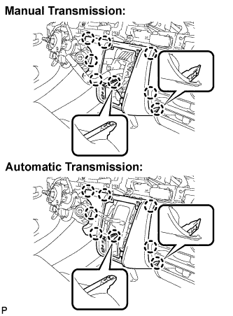
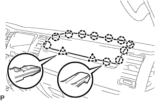
Disengage the 8 claws and remove the instrument panel finish panel lower center.
-
-
REMOVE FLOOR SHIFT SHIFT LEVER ASSEMBLY (for Manual Transmission)
For 5L-E Click here
For 2KD-FTV, 2TR-FE Click here
-
REMOVE SHIFT LOCK CONTROL UNIT ASSEMBLY (for Automatic Transmission)
For 2KD-FTV Click here
For 2TR-FE Click here
-
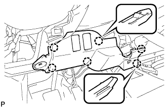
REMOVE AIR CONDITIONER PANEL SUB-ASSEMBLY
-
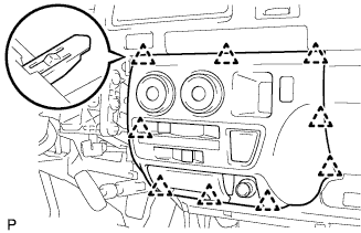
Release the 9 clips and the air conditioner panel sub-assembly.
-
Disconnect the connector and remove the air conditioner panel sub-assembly.
-
Release clamp.
-
Disengage the 2 claws and then remove the boost ventilator control cable sub-assembly.
-
Disengage the 2 claws and then remove the defroster damper control cable sub-assembly.
-
Remove the 2 screws and remove the heater control hose.
-
-
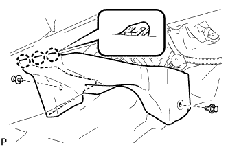
REMOVE GLOVE COMPARTMENT DOOR ASSEMBLY
-
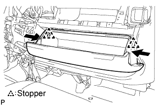
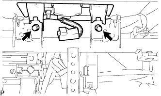
Push the positions indicated by the arrows in the illustration inward to release the 2 stoppers.
-
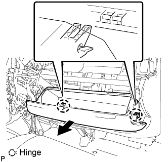
Pull the glove compartment door assembly in the direction indicated by the arrow shown in the illustration and disengage the 2 hinges.
-
Remove the glove compartment door assembly.
-
-
REMOVE FRONT PASSENGER AIRBAG ASSEMBLY (w/ Front Passenger Airbag)
-
Separate the clamp from the reinforcement.
-
Disconnect the airbag connector.
-
Remove the 2 bolts from the reinforcement.
-
Separate the clip and clamp, and remove the instrument panel passenger airbag assembly.
-
-
REMOVE HAZARD WARNING SIGNAL SWITCH ASSEMBLY
-
REMOVE FRONT ASSIST GRIP NO.1 PLUG
-
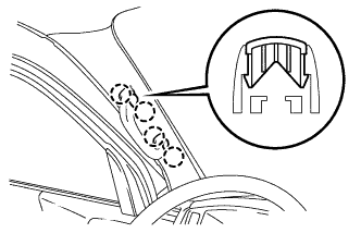
Using a screwdriver, disengage the assist grip plug No.1.
Tech Tips
-
Tape the screwdriver tip before use.
-
Use the same procedures described for the RH side.
-
-
-
REMOVE ASSIST GRIP ASSEMBLY
-
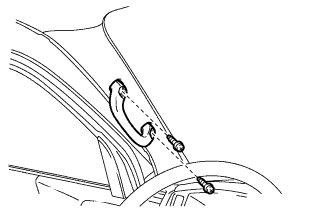
Remove the 2 screws and assist grip.
Tech Tips
Use the same procedures described for the RH side.
-
-
REMOVE FRONT PILLAR GARNISH LH
w/o Rear Cooler Click here
w/ Rear Cooler Click here
-
REMOVE FRONT PILLAR GARNISH RH
-
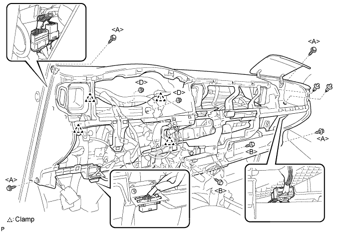
REMOVE INSTRUMENT PANEL ASSEMBLY
-
Remove the 4 bolts <A> and 3 screws <B>.
-
Remove the 2 nuts <D> and 2 clips.
-
Disengage the clamps.
-
Disengage the DLC3 connector from the wire harness clamp bracket.
-
Disconnect the instrument panel wire No.2 connector. (passenger side)
-
Pull the instrument panel sub-assembly towards you and check that no wire harnesses are stuck in the body.
Note
Do not damage the instrument panel assembly with the steering column etc. when taking it out of the vehicle.
-
Disconnect the instrument panel wire No.2 connector. (driver side)
-