OUTER REAR VIEW MIRROR REASSEMBLY

Tech Tips
-
Use the same procedure for RHD and LHD vehicles.
-
The procedure listed below is for LHD vehicles.
-
Use the same procedure for the RH and LH sides.
-
The procedure listed below is for the LH side.
-
INSTALL OUTER MIRROR RETRACTOR LH (w/ Retract Mirror)
-
Install the actuator sub-assembly.
-
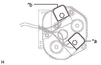
Text in Illustration *a Black *b Gray Attach the 2 claws to connect the 2 connectors of a new wire harness sub-assembly as shown in the illustration.
-
Install the actuator sub-assembly with the 3 screws.
-
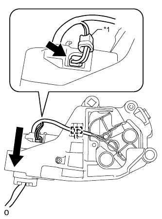
Text in Illustration *1 Rubber Cover Pull the wire harness sub-assembly through the frame sub-assembly as shown in the illustration.
-
Connect the connector to install the rubber cover.
-
Attach the wire harness sub-assembly to the clamp.
-
-
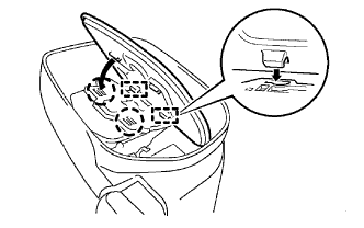
Install the body sub-assembly with the 4 screws.
-
Using a T25 "TORX" socket wrench, install the base plate with a new "TORX" screw.
- Torque:
- 3.8 N*m { 39 kgf*cm, 34 in.*lbf }
-
Install the base sub-assembly.
-
Using a T25 "TORX" socket wrench, install the base sub-assembly with 3 new "TORX" screws.
- Torque:
- 3.8 N*m { 39 kgf*cm, 34 in.*lbf }
-
Attach the 5 claws to install a new gasket.
-
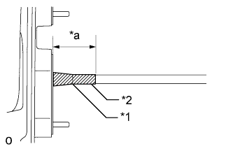
Text in Illustration *1 Mark *2 Tape *a 40 to 50 mm Align the mark of the wire harness sub-assembly with the end of the protrusion of the gasket into which the wire harness is inserted, and then secure the wire harness with tape as shown in the illustration.
Note
-
Wrap at least 2 layers of tape around the wire harness.
-
Make sure there is no gap between the tape and wire harness when applying tape.
-
-
-
Install the clamp.
-
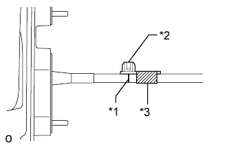
Text in Illustration *1 Mark *2 Clamp *3 Tape Align the clamp with the mark and secure it with tape as shown in the illustration.
-
-
Assemble the connector.
-
While referring to the chart below, insert the pins of the wire harness sub-assembly into the back of a new adapter until they lock.
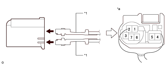
Text in Illustration *1 Wire Harness Pin - - *a Rear View of Connector - - Note
-
When inserting the pins of the wire harness, compare a new connector with the connector that was cut off during removal and make sure that the arrangement of the wire colors of the pins is the same as before.
-
Confirm that the pins of the wire harness are securely locked and cannot be pulled out.
-
When a pin of the wire harness is locked, it cannot be pulled out. Therefore, be sure to insert each pin into the correct location.
Wire Harness Color Chart for LH: 1 2 3 4 5 6 7 Blue Green Purple - - Brown Red for RH: 1 2 3 4 5 6 7 Blue Green Purple - - Brown Red -
-
-
-
INSTALL OUTER MIRROR LH (w/ Retract Mirror)
-
Attach the 2 guides and 2 claws to install the outer mirror LH.
-