ECD SYSTEM TC and CG Terminal Circuit
DESCRIPTION
Terminals TC and CG are located in the DLC3.
The DLC3 is located under the instrument panel under cover. When terminals TC and CG are connected, DTC in normal mode or test mode can be read from the Malfunction Indicator Lamp (MIL) in the combination meter.
Also, terminal SIL is located in the DLC3. This terminal is used by the M-OBD communication with intelligent tester.
WIRING DIAGRAM
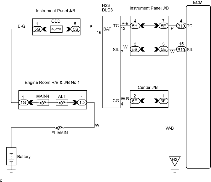
INSPECTION PROCEDURE
PROCEDURE
-
CHECK DLC3 (CHECK VOLTAGE)
-
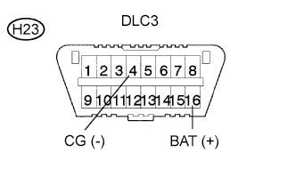
Measure the voltage according to the value(s) in the table below.
Standard voltage Tester Connection Specified condition BAT (H23-16) - CG (H23-4) 9 to 14 V
NG 
CHECK DLC3 Click here
OK 
-
-
CHECK HARNESS AND CONNECTOR (ECM - DLC3)
-
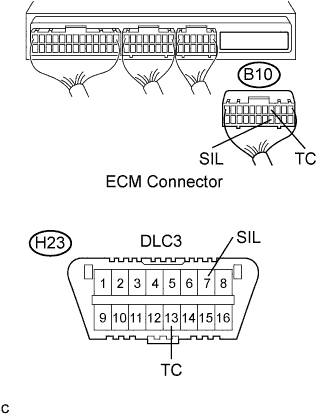
Disconnect the ECM B10 connector.
-
Measure the resistance according to the value(s) in the table below
Standard resistance (Check for open) Tester Connection Specified Condition SIL (H23-7) - SIL (B10-15) Below 1 Ω TC (H23-13) - TC (B10-4) Below 1 Ω Standard resistance (Check for short) Tester Connection Specified Condition SIL (B10-15) - Body ground 10 kΩ or higher TC (B10-4) - Body ground 10 kΩ or higher
NG 
REPAIR OR REPLACE HARNESS OR CONNECTOR
OK 
REPLACE ECM
-
-
CHECK DLC3
-
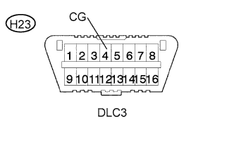
Measure the resistance according to the value(s) in the table below.
Standard resistance Tester Connection Specified condition CG (H23-4) - Body ground Below 1 Ω
NG
REPAIR OR REPLACE HARNESS OR CONNECTOR
OK
-
-
CHECK FUSE (OBD FUSE)
-
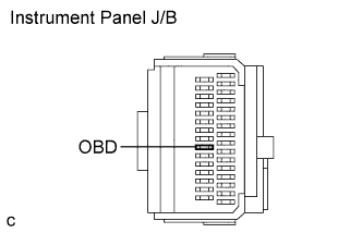
Remove the OBD fuse from the instrument panel J/B.
-
Measure the resistance according to the value(s) in the table below.
Standard resistance Tester Connection Specified condition OBD fuse Below 1 Ω (continuity)
NG
REPLACE FUSE (OBD FUSE)
OK
CHECK AND REPLACE HARNESS AND CONNECTOR (DLC3 - BATTERY)
-