ECD SYSTEM Starter Signal Circuit
DESCRIPTION
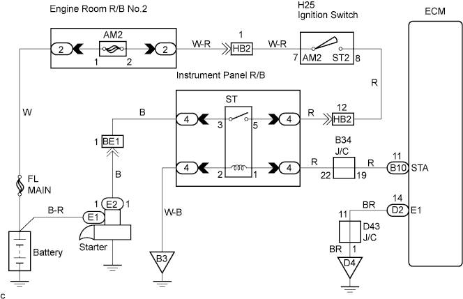
When the engine is being cranked, the intake air flow is slow, so fuel vaporization is poor. A rich mixture is therefore necessary in order to achieve good start ability. While the engine is being cranked, the battery positive voltage is applied to terminal STA of the ECM. The starter signal is mainly used to increase the fuel injection volume for the starting injection control and after-start injection control.
WIRING DIAGRAM
INSPECTION PROCEDURE
Tech Tips
This diagnostic chart is based on the premise that the engine is being cranked under normal conditions. If the engine does not crank, proceed to the problem symptoms table Click here.
When using intelligent tester:
PROCEDURE
-
READ VALUE OF INTELLIGENT TESTER (STA SIGNAL)
-
Connect the intelligent tester to the DLC3.
-
Turn the ignition switch ON.
-
Select the item "Powertrain/Engine and ECT/Data List/Starter SIG".
-
Read STA signal on the intelligent tester while the starter operates.
Result Ignition Switch Position LOCK, ACC, ON STA STA Signal OFF ON
NG 
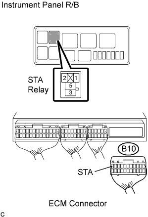
CHECK HARNESS AND CONNECTOR (ECM - STARTER RELAY) Click here
OK 
PROCEED TO NEXT CIRCUIT INSPECTION SHOWN IN PROBLEM SYMPTOMS TABLE
-
-
CHECK HARNESS AND CONNECTOR (ECM - STARTER RELAY)
-
Disconnect the ECM B10 connector.
-
Remove the starter relay from the instrument panel R/B.
-
Measure the resistance according to the value(s) in the table below.
Standard resistance Tester Connection Specified Condition (Starter relay terminal 1 of R/B) - STA (B10-11) Below 1 Ω (Starter relay terminal 2 of R/B) - Body ground Below 1 Ω
NG 
REPAIR OR REPLACE HARNESS OR CONNECTOR
OK 
-
-
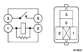
INSPECT STARTER RELAY
-
Remove the starter relay from the instrument panel R/B.
-
Check the starter relay resistance.
Standard resistance Tester Connection Specified Condition 3 - 5 10 kΩ or higher 3 - 5 Below 1 Ω
(when battery voltage applied to terminals 1 and 2)
NG
REPLACE STARTER RELAY
OK
REPLACE ECM
-
When not using intelligent tester:
PROCEDURE
-
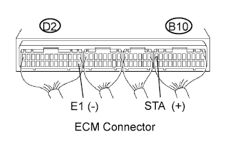
INSPECT ECM (CHECK VOLTAGE)
-
Turn the ignition switch ON.
-
Measure the voltage according to the value(s) in the table below.
Standard voltage Tester Connection Connection Specified Condition STA (B10-11) - E1 (D2-14) Cranking 6.0 V or more
NG
CHECK HARNESS AND CONNECTOR (ECM - STARTER RELAY) Click here
OK
PROCEED TO NEXT CIRCUIT INSPECTION SHOWN IN PROBLEM SYMPTOMS TABLE
-
-
CHECK HARNESS AND CONNECTOR (ECM - STARTER RELAY)
-
Disconnect the ECM B10 connector.
-
Remove the starter relay from the instrument panel R/B.
-
Measure the resistance according to the value(s) in the table below.
Standard resistance (Check for open) Tester Connection Specified Condition (Starter relay terminal 1 of R/B) - STA (B10-11) Below 1 Ω (Starter relay terminal 2 of R/B) - STA (B10-11) Below 1 Ω
NG
REPAIR OR REPLACE HARNESS OR CONNECTOR
OK
-
-
INSPECT STARTER RELAY
-
Remove the starter relay from the instrument panel R/B.
-
Check the starter relay resistance.
Standard resistance Tester Connection Specified Condition 3 - 5 10 kΩ or higher 3 - 5 Below 1 Ω
(when battery voltage applied to terminals 1 and 2)
NG
REPLACE STARTER RELAY
OK
REPLACE ECM
-