ECD SYSTEM Pre-heating Control Circuit
DESCRIPTION
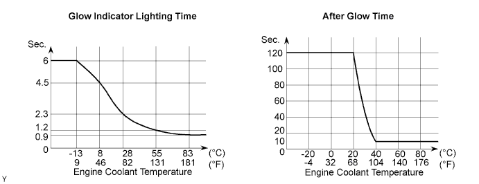
When the ignition switch turns ON, the ECM calculates the glow indicator lighting time/heating corresponding to the coolant temperature at that time and turns on the glow indicator light/glow plug relay.
As the ceramics is used for a glow plug material, the current control is not performed.
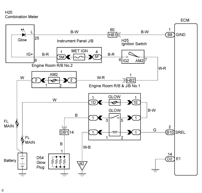
WIRING DIAGRAM
INSPECTION PROCEDURE
PROCEDURE
-
CHECK GLOW INDICATOR LIGHT
-
Turn the ignition switch ON.
-
Check that the glow indicator light comes on.
OK The glow indicator light remains on for 0.5 sec. or more and then goes off.
NG 
INSPECT ECM (CHECK VOLTAGE) Click here
OK 
-
-
INSPECT GLOW PLUG (INSTALLATION)
-
Check that the glow plug and glow plug wire are securely installed.
OK The glow plug and glow plug wire are securely installed.
NG 
TIGHTEN GLOW PLUG
OK
-
-
INSPECT GLOW PLUG
-
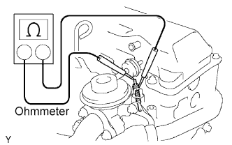
Measure the resistance according to the value(s) in the table below.
Standard resistance 0.72 Ω at 20°C (68°F) Tech Tips
The higher the temperature is the smaller the resistance becomes and vice versa.
NG
REPLACE GLOW PLUG
OK
-
-
CHECK FOR INDICATOR LIGHTING TIME AND AFTER GLOW TIME
NG
REPLACE ECM
OK
-
READ OUTPUT DTC
-
Read the DTC Click here.
Result DTC is not output A DTC is output B
B
GO TO RELEVANT DTC CHART
A
-
-
INSPECT GLOW PLUG RELAY
-
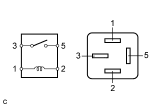
Measure the resistance according to the value(s) in the table below.
Standard resistance Tester Connection Specified Condition 3 - 5 10 kΩ or higher
(No continuity)
3 - 5 Below 1 Ω
(Apply B+ between terminals 1 and 2)
NG
REPLACE GLOW PLUG RELAY
OK
-
-
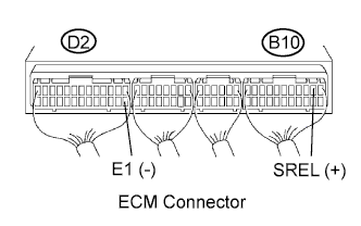
INSPECT ECM (CHECK VOLTAGE)
-
Turn the ignition switch to the START position.
-
Measure the voltage according to the value(s) in the table below.
Standard voltage Tester Connection Connection Specified Condition SREL (B10-2) - E1 (D2-14) Cranking 9 to 14 V
NG
REPLACE ECM
OK
-
-
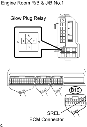
CHECK HARNESS AND CONNECTOR (ECM - GLOW PLUG RELAY, GLOW PLUG RELAY - BODY GROUND)
-
Disconnect the B10 ECM connector.
-
Disconnect the glow plug relay from the engine room R/B & J/B No.1.
-
Measure the resistance according to the value(s) in the table below.
Standard resistance (Check for open) Tester Connection Specified Condition (GLOW relay terminal 2 of R/B) - SREL (B10-2) Below 1 Ω (GLOW relay terminal 1 of R/B) - Body ground Below 1 Ω Standard resistance (Check for short) Tester Connection Specified Condition SREL (B10-2) - Body ground 10 kΩ or higher
NG
REPAIR OR REPLACE HARNESS OR CONNECTOR
OK
-
-
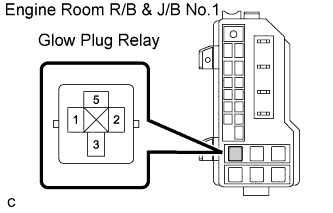
CHECK HARNESS AND CONNECTOR (GLOW PLUG RELAY - GLOW PLUG, GLOW PLUG RELAY - BATTERY)
-
Disconnect the battery negative cable.
-
Disconnect the battery positive cable.
-
Remove the glow plug relay from the engine room R/B & J/B No. 1.
-
Disconnect the glow plug wire.
-
Measure the resistance according to the value(s) in the table below.
Standard resistance (Check for open) Tester Connection Specified Condition (Glow plug relay terminal 3 of R/B) - Glow plug wire Below 1 Ω (Glow plug relay terminal 5 of R/B) - Positive terminal of the battery Below 1 Ω Note
After reconnecting the battery cable, the radio and clock should be adjusted as they were previously.
NG
REPAIR OR REPLACE HARNESS OR CONNECTOR
OK 
PROCEED TO NEXT CIRCUIT INSPECTION SHOWN IN PROBLEM SYMPTOMS TABLE
-
-
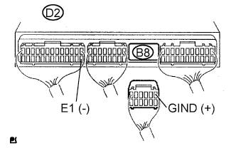
INSPECT ECM (CHECK VOLTAGE)
-
Disconnect the B8 ECM connector.
-
Turn the ignition switch ON.
-
Measure the voltage according to the value(s) in the table below.
Standard voltage Tester Connection Specified Condition GIND (B8-1) - E1 (D2-14) 9 to 14 V
NG
INSPECT COMBINATION METER (CHECK VOLTAGE) Click here
OK
REPLACE ECM
-
-
INSPECT COMBINATION METER (CHECK VOLTAGE)
-
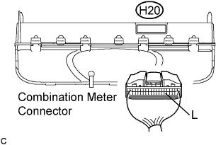
Disconnect the combination meter connector.
-
Turn the ignition switch ON.
-
Measure the voltage according to the value(s) in the table below.
Standard voltage Tester Connection Specified Condition L (H20-25) - Body ground 9 to 14 V
NG
INSPECT COMBINATION METER (CHECK VOLTAGE) Click here
OK
-
-
CHECK HARNESS AND CONNECTOR (ECM - COMBINATION METER)
-
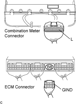
Disconnect the B8 ECM connector.
-
Disconnect the combination meter connector.
-
Measure the resistance according to the value(s) in the table below.
Standard resistance Tester Connection Specified Condition L (H20-25) - GIND (B8-1) Below 1 Ω
NG
REPAIR OR REPLACE HARNESS OR CONNECTOR
OK
CHECK FOR INTERMITTENT PROBLEMS
-
-
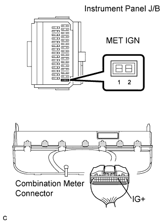
INSPECT COMBINATION METER (CHECK VOLTAGE)
-
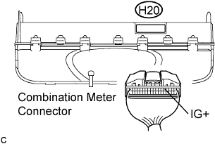
Disconnect the combination meter connector.
-
Turn the ignition switch ON.
-
Measure the voltage according to the value(s) in the table below.
Standard voltage Tester Connection Specified Condition IG+ (H20-6) - Body ground 9 to 14 V
NG
CHECK FUSE (MET IGN FUSE) Click here
OK
REPLACE COMBINATION METER
-
-
CHECK FUSE (MET IGN FUSE)
-
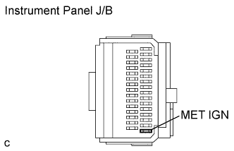
Remove the MET IGN fuse from the instrument panel J/B.
-
Measure the resistance according to the value(s) in the table below.
Standard resistance Tester Connection Specified Condition MET IGN fuse Below 1 Ω (Continuity)
NG
REPLACE FUSE (MET IGN FUSE)
OK
-
-
CHECK HARNESS AND CONNECTOR (ECM - COMBINATION METER, COMBINATION METER - GAUGE FUSE)
-
Disconnect the combination meter connector.
-
Remove the MET IGN fuse from the instrument panel J/B.
-
Measure the resistance according to the value(s) in the table below.
Standard resistance (Check for open) Tester Connection Specified Condition (MET IGN fuse terminal 1 of J/B ) - IG+ (H20-6) Below 1 Ω
NG
REPAIR OR REPLACE HARNESS OR CONNECTOR
OK
CHECK AND REPLACE HARNESS AND CONNECTOR (MET IGN FUSE - BATTERY)
-