ECD SYSTEM TERMINALS OF ECM


Tech Tips
Each ECM terminal's standard normal voltage is shown in the table below.
In the table, first follow the information under "Condition". Look under "Symbols (Terminal No.)" for the terminals to be inspected. The standard normal voltage between the terminals is shown under "STD Voltage". Use the illustration above as a reference for the ECM terminals.
| Symbols (Terminal No.) | Wiring Color | Terminal Description | Condition | STD Voltage |
|---|---|---|---|---|
| BATT (B10-1) - E1 (D2-14) | B-R - BR | Battery (for measuring the battery voltage and for the ECM memory) | Always | 9 to 14 V |
| SREL (B10-2) - E01 (D2-13) | G - BR | Glow plug relay | Cranking | 9 to 14 V |
| SREL (B10-2) - E01 (D2-13) | G - BR | Glow plug relay | Idling (engine start and after 600 sec.) |
0 to 1.5 V |
| MREL (B10-3) - E1 (D2-14) | G-Y - BR | EFI relay | IG switch ON | 9 to 14 V |
| MREL (B10-3) - E1 (D2-14) | G-Y - BR | EFI relay | IG switch OFF (after IG switch OFF for 2 sec.) |
0 to 1.5 V |
| TC (B10-4) - E1 (D2-14) | P - BR | Terminal TC of DLC3 | IG switch ON | 9 to 14 V |
| W (B10-5) - E1 (D2 -14) | G-R - BR | MIL | Check engine warning light lights up | 0 to 3 V |
| W (B10-5) - E1 (D2-14) | G-R - BR | MIL | Except check engine warning light lights up | 9 to 14 V |
| RFC (B10-7) - E1 (D2-14) | LG-B - BR | Cooling fan ECU | IG switch ON or fan is rotating | Pulse generation (See waveform 1) |
| THWO (B10-8) - E1 (D2-14) | Y - BR | Combination meter | IG switch ON | Pulse generation (See waveform 2) |
| SPD (B10-9) - E1 (D2-14) | P-L- BR | Speed signal from combination meter | IG switch ON, Rotate driving wheel slowly | Pulse generation (See waveform 3) |
| STA (B10 -11) - E1 (D2-14) | R - BR | Starter signal | Cranking | 6 V or more |
| +B (B10 -12) - E1 (D2-14) | B-R - BR | Power source of ECM | IG switch ON | 9 to 14 V |
| FAN (B10-13) - E1 (D2-14) | W-L - BR | Fan relay | Sub fan is rotating | 0 to 3 V |
| FAN (B10-13) - E1 (D2-14) | W-L - BR | Fan relay | Sub fan is not rotating | 9 to 14 V |
| IGSW (B10-14) - E1 (D2-14) | B-R - BR | Engine switch | IG switch ON | 9 to 14 V |
| SIL (B10-15) - E1 (D2-14) | W - BR | Terminal SIL of DLC3 | Connect intelligent tester to DLC3 | Pulse generation |
| STP (B10-19) - E1 (D2-14) | R-W - BR | Stop light switch | Brake pedal depressed | 9 to 14 V |
| STP (B10-19) - E1 (D2-14) | R-W - BR | Stop light switch | Brake pedal released | Below 1.5 V |
| HSW (B10-20) - E1 (D2-14) | L-W - BR | Idle up switch | Idle up switch ON | Below 2.5 V |
| HSW (B10-20) - E1 (D2-14) | L-W - BR | Idle up switch | Idle up switch OFF | 9 to 14 V |
| ALT (B10-22) - E1 (D2-14) | W - BR | Generator (alternator) duty ratio | Idling | Pulse generation (See waveform 4) |
| GIND (B8-1) - E1 (D2-14) | B-W - BR | Glow indicator light | Glow indicator light lights up | 0 to 3 V |
| GIND (B8-1) - E1 (D2-14) | B-W - BR | Glow indicator light | Except glow indicator light lights up | 9 to 14 V |
| AC1 (B8-2) - E1 (D2-14) | R-B - BR | A/C amplifier | A/C switch ON (at magnet clutch ON) |
Below 1.5 V |
| AC1 (B8-2) - E1 (D2-14) | R-B - BR | A/C amplifier | A/C switch OFF | 7.5 to 14 V |
| VPA (B8-5) - EPA (B8-4) | L - W-L | Accelerator pedal position sensor (for engine control) |
IG switch ON, accelerator pedal released | 0.5 to 1.1 V |
| VPA (B8-5) - EPA (B8-4) | L - W-L | Accelerator pedal position sensor (for engine control) |
IG switch ON, accelerator pedal depressed | 2.6 to 4.5 V |
| VCPA (B8-6) - EPA (B8-4) | W - W-L | Power source of accelerator pedal position sensor (for VPA) |
IG switch ON | 4.5 to 5.5 V |
| TACH (B8-7) - E1 (D2-14) | B-Y - BR | Engine speed | Idling | Pulse generation (See waveform 5) |
| ACT (B8-8) - E1 (D2-14) | G-W - BR | A/C amplifier | IG switch ON | 9 to 14 V |
| ACT (B8-8) - E1 (D2-14) | G-W - BR | A/C amplifier | At A/C cut controlled (Driving below 30 km/h (18.6 mph), accelerator pedal fully depressed for 5 sec.) | 0 to 3 V |
| ST1 - (B8-11) - E1 (D2-14) | R-L - BR | Stop light switch | Brake pedal depressed | Below 1.5 V |
| ST1 - (B8-11) - E1 (D2-14) | R-L - BR | Stop light switch | Brake pedal released | 9 to 14 V |
| VPA2 (B8-12) - EPA (B8-4) | B - W-L | Accelerator pedal position sensor (for sensor malfunction detection) | IG switch ON, accelerator pedal released | 1.2 to 2.0 V |
| VPA2 (B8-12) - EPA (B8-4) | B - W-L | Accelerator pedal position sensor (for sensor malfunction detection) | IG switch ON, accelerator pedal depressed | 3.4 to 5.3 V |
| VC (D4-1) - E2 (D4-9) | L-B - Y-R | Power source of sensor (a specific voltage) | IG switch ON | 4.5 to 5.5 V |
| PIM (D4-2) - E2 (D4-9) | P - Y-R | Pressure sensor | Apply vacuum 60 kPa (450 mmHg, 17.7 in.Hg) |
0.2 to 0.8 V |
| PIM (D4-2) - E2 (D4-9) | P - Y-R | Pressure sensor | Apply vacuum 207 kPa (1,550 mmHg, 61.0 in.Hg) |
4.2 to 4.8 V |
| THA (D4-3) - E2 (D4-9) | R-L - Y-R | Intake air temperature sensor | Idling, air intake temp. 0°C (32°F) to 80°C (176°F) | 0.5 to 3.4 V |
| THW (D4-4) - E2 (D4-9) | R-W - Y-R | Engine coolant temperature sensor | Idling, engine coolant temp. 60°C (140°F) to 120°C (248°F) | 0.2 to 1.0 V |
| THF (D4-5) - E2 (D4-9) | R - Y-R | Fuel temperature sensor | IG switch ON (at engine cold) | 0.5 to 3.4 V |
| DATA (D4-6) - E1 (D2-14) | Y - BR | Injection pump | For 0.5 sec. after IG switch ON | Pulse generation |
| PR2 (D4-8) - E1 (D2-14) | Y-G - BR | Pressure switch | Pressure switch ON (A/C pressure is normal) | Below 1.5 V |
| PR2 (D4-8) - E1 (D2-14) | Y-G - BR | Pressure switch | Pressure switch OFF (A/C pressure is low) | 9 to 14 V |
| RTHW (D4-12) - E2 (D4-9) | L-R - Y-R | Radiator side engine coolant temperature sensor | Idling, radiator side engine coolant temp. 60°C (140°F) to 120°C (248°F) | 0.2 to 1.0 V |
| CLK (D4-14) - E1 (D2-14) | L - Y-R | Injection pump | For 0.5 sec. after IG switch ON | Pulse generation |
| THOP (D4-15) - E1 (D2-14) | L - BR | Intake shutter fully opened switch | Idling (engine warmed up) | 9 to 14 V |
| THOP (D4-15) - E1 (D2-14) | L - BR | Intake shutter fully opened switch | IG switch ON (once within 5 sec.) | 0 to 3 V |
| LU-B (D2-7) - E01 (D2-13) | G - BR | Intake restrictor valve control motor (Intake shutter) |
Racing (engine warmed up) | Pulse generation (See waveform 6) |
| LU+B (D2-8) - E01 (D2-13) | R - BR | Intake restrictor valve control motor (Intake shutter) |
Racing (engine warmed up) | Pulse generation (See waveform 6) |
| LU-A (D2-9) - E01 (D2-13) | W - BR | Intake restrictor valve control motor (Intake shutter) |
Racing (engine warmed up) | Pulse generation (See waveform 6) |
| LU+A (D2-10) - E01 (D2-13) | B - BR | Intake restrictor valve control motor (Intake shutter) |
Racing (engine warmed up) | Pulse generation (See waveform 6) |
| TCV (D2-11) - E01 (D2-13) | B-W - BR | Timing control valve | IG switch ON | 9 to 14 V |
| TCV (D2-11) - E01 (D2-13) | B-W - BR | Timing control valve | Idling | Pulse generation (See waveform 7) |
| SPV+ (D2-12) - E1 (D2-14) | B - BR | Spill control valve | IG switch ON | 9 to 14 V |
| SPV+ (D2-12) - E1 (D2-14) | B - BR | Spill control valve | Idling | Pulse generation |
| TDC+ (D2-17) - TDC- (D2-16) | R - G | Crankshaft position sensor | Idling | Pulse generation (See waveform 8) |
| NE+ (D2-19) - NE- (D2-18) | Y - L | Engine speed sensor | Idling | Pulse generation (See waveform 8) |
| SPV- (D2-25) - E1 (D2-14) | B-L - BR | Spill control valve | Idling | Pulse generation (See waveform 9) |
-
Waveform 1 (Reference):
-
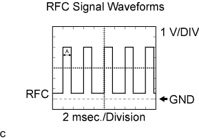
Cooling fan signal.
Terminal RFC - E1 Tool Setting 1 V/DIV., 2 ms/DIV. Condition When fan operating Tech Tips
Waveform time A changes according to coolant temperature.
-
-
Waveform 2 (Reference):
-
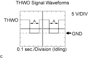
A/C amplifier signal.
Terminal THWO - E1 Tool Setting 5 V/DIV., 0.1 s/DIV. Condition During idling Tech Tips
Waveform time A changes according to coolant temperature.
-
-
Waveform 3 (Reference):
-
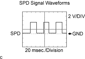
Speed signal.
Terminal SPD - E1 Tool Setting 2 V/DIV., 20 ms/DIV. Condition When driving at approx. 20 km/h (12.4 mph). Tech Tips
-
As vehicle speed increases, the waveform becomes shorter.
-
As vehicle speed increases, the waveforms amplitude become greater.
-
-
-
Waveform 4 (Reference):
-
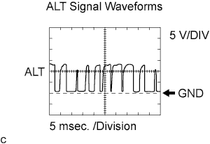
Generator signal.
Terminal ALT - E1 Tool Setting 5 V/DIV., 5 ms/DIV. Condition During idling
-
-
Waveform 5 (Reference):
-
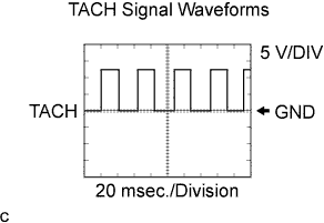
Engine speed signal.
Terminal TACH - E1 Tool Setting 5 V/DIV., 20 ms/DIV. Condition
-
After warming up
-
During idling
Tech Tips
As engine speed increases, the waveform becomes shorter.
-
-
-
Waveform 6 (Reference):
-
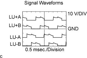
Intake restrictor valve control motor signal.
Terminal LU+A, LU-A, LU+B, LU-B - E01 Tool Setting 10 V/DIV., 0.5 ms/DIV. Condition During engine racing
-
-
Waveform 7 (Reference):
-
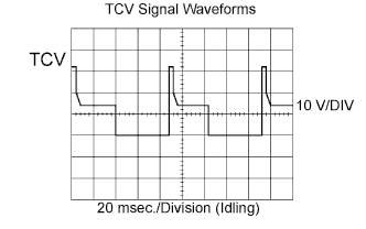
Timing control value signal.
Terminal TCV - E01 Tool Setting 10 V/DIV., 10 ms/DIV. Condition During idling
-
-
Waveform 8 (Reference):
-
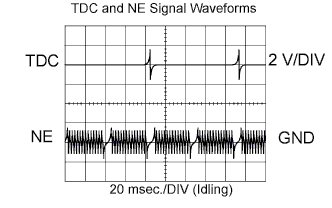
Crankshaft position sensor signal.
Terminal TDC+ - TDC-
NE+ - NE-
Tool Setting 2 V/DIV., 20 ms/DIV. Condition During idling
-
-
Waveform 9 (Reference):
-
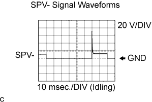
Spill control valve signal.
Terminal SPV- - E1 Tool Setting 20 V/DIV., 10 ms/DIV. Condition During idling
-