ECD SYSTEM, Diagnostic DTC:14

| DTC Code | DTC Name |
|---|---|
| 14 | Timing Control System Malfunction |
DESCRIPTION
The ECM controls the injection timing by actuating the timing control valve. The timing control valve is mounted on the injection pump and delay one by dutys control of pump internal fuel pressure.
The ECM detects the injection advance angle by TDC and NE signals.
| DTC No. | DTC Detection Condition | Trouble Area |
|---|---|---|
| 14 | During and after engine warm up, actual injection timing is different from target value of ECM calculated for several sec. |
|
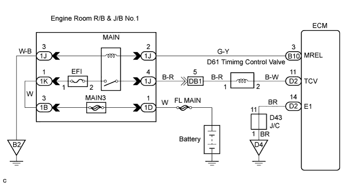
WIRING DIAGRAM
INSPECTION PROCEDURE
PROCEDURE
-
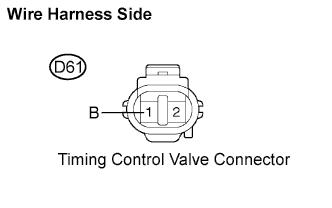
INSPECT TIMING CONTROL VALVE
-
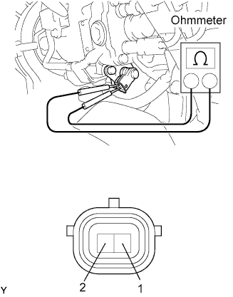
Disconnect the timer control valve connector.
-
Measure the resistance according to the value(s) in the table below.
Standard resistance Tester Connection Specified Condition 1 - 2 10 to 14 Ω (20°C (68°F))
NG 
REPLACE TIMING CONTROL VALVE
OK 
-
-
INSPECT ECM (CHECK VOLTAGE)
-
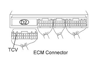
Disconnect the ECM D2 connector.
-
Turn the ignition switch ON.
-
Measure the voltage according to the value(s) in the table below.
Standard voltage Tester Connection Specified Condition TCV (D2-11) - Body ground 9 to 14 V
NG 
INSPECT TIMING CONTROL VALVE (POWER SOURCE) Click here
OK
-
-
INSPECT ECM
-
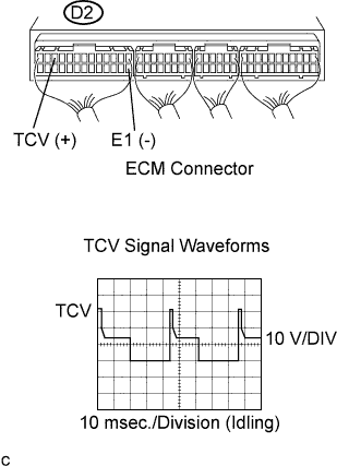
Turn the ignition switch ON.
-
Measure the voltage according to the value(s) in the table below.
Standard voltage Tester Connection Specified Condition TCV (D2-11) - E1 (D2-14) 9 to 14 V -
While idling, measure the waveform according to the value( s) in the table below.
OK Tester Connection Specified Condition TCV (D2-11) - E1 (D2-14) Correct waveform shown
NG
REPLACE ECM
OK
-
-
CHECK FUEL FILTER ASSEMBLY
NG
REPLACE FUEL FILTER ASSEMBLY
OK
-
CHECK FUEL LEAK
-
Visually check the injection pump, each injector and fuel line for fuel leaks.
OK No leakage
NG
REPAIR OR REPLACE FUEL LEAK
OK 
CHECK AND REPLACE INJECTION PUMP ASSEMBLY
-
-
INSPECT TIMING CONTROL VALVE (POWER SOURCE)
-
Disconnect the timing control valve connector.
-
Turn the ignition switch ON.
-
Measure the voltage according to the value(s) in the table below.
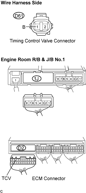
Standard voltage Tester Connection Specified Condition B (D61-1) - Body ground 9 to 14 V
NG
CHECK HARNESS AND CONNECTOR (ECM - MAIN RELAY) Click here
OK
REPAIR OR REPLACE HARNESS OR CONNECTOR (TIMING CONTROL VALVE - ECM)
-
-
CHECK HARNESS AND CONNECTOR (ECM - MAIN RELAY)
-
Disconnect the timing control valve connector.
-
Disconnect the ECM D2 connector.
-
Disconnect the integration relay 1J connector.
-
Measure the resistance according to the value(s) in the table below.
Standard resistance (Check for open) Tester Connection Specified Condition B (D61-1) - (1J-4) Below 1 Ω Standard resistance (Check for short) Tester Connection Specified Condition TCV (D2-11) - Body ground 10 kΩ or higher B (D61-1) - Body ground 10 kΩ or higher
NG
REPAIR OR REPLACE HARNESS OR CONNECTOR
OK
CHECK FOR ECM POWER SOURCE CIRCUIT
-