ECD SYSTEM, Diagnostic DTC:13

| DTC Code | DTC Name |
|---|---|
| 13 | Engine Speed Sensor Circuit Malfunction (NE Circuit) |
DESCRIPTION
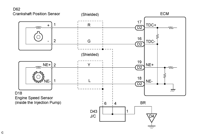
The engine speed sensor in the Engine Control System contains a signal plate and a pickup coil for NE signal. The NE signal plate has 56 teeth and is mounted in the injection pump. The NE signal sensor generates 56 signals for every 2 engine revolutions. The ECM detects the engine speed and cam lift position of the injection pump. The ECM uses TDC signal and NE signals for injection timing control. And NE signal is used for injection volume control, also.
| DTC No. | DTC Detection Condition | Trouble Area |
|---|---|---|
| 13 | No NE signal to ECM for 0.5 sec. or more at 680 rpm or more |
|
| No NE signal to ECM for 2.0 sec. or more during cranking |
WIRING DIAGRAM
INSPECTION PROCEDURE
PROCEDURE
-
INSPECT ENGINE SPEED SENSOR
-
Check the engine speed sensor installation.
-
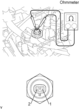
Disconnect the engine speed sensor connector.
-
Measure the resistance according to the value(s) in the table below.
Standard resistance Tester Connection Specified Condition 1 - 2 205 to 255 Ω (20°C (68°F)) Tech Tips
The engine speed sensor is integrated with the injection pump assembly. If the engine speed sensor is replaced, the injection pump assembly must be replaced in whole.
NG 
CHECK AND REPLACE INJECTION PUMP ASSEMBLY
OK 
-
-
CHECK ECM
-
Connect the engine speed sensor connector.
-
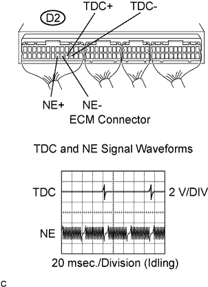
While cranking or idling, measure the waveform according to the value(s) in the table below.
OK Tester Connection Specified Condition NE+ (D2-19) - NE- (D2-18) Correct waveform shown TDC+ (D2-17) - TDC- (D2-16) Correct waveform shown
NG 
CHECK HARNESS AND CONNECTOR (ECM - ENGINE SPEED SENSOR) Click here
OK 
REPLACE ECM
-
-
CHECK HARNESS AND CONNECTOR (ECM - ENGINE SPEED SENSOR)
-
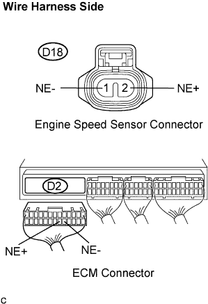
Disconnect the engine speed sensor connector.
-
Disconnect the ECM D2 connector.
-
Measure the resistance according to the value(s) in the table below.
Standard resistance (Check for open) Tester Connection Specified Condition NE+ (D18-2) - NE+ (D2-19) Below 1 Ω NE- (D18-1) - NE- (D2-18) Below 1 Ω Standard resistance (Check for short) Tester Connection Specified Condition NE+ (D2-19)- NE- (D2-18) 10 kΩ or higher NE+ (D2-19) - Body ground 10 kΩ or higher NE- (D2-18) - Body ground 10 kΩ or higher
NG
REPAIR OR REPLACE HARNESS OR CONNECTOR
OK
CHECK FOR INTERMITTENT PROBLEMS
-