ECD SYSTEM, Diagnostic DTC:P0405/96, P0406/96

| DTC Code | DTC Name |
|---|---|
| P0405/96 | Exhaust Gas Recirculation Sensor "A" Circuit Low |
| P0406/96 | Exhaust Gas Recirculation Sensor "A" Circuit High |
DESCRIPTION
The EGR valve position sensor is mounted on the EGR valve and used for detecting the lift amount of the valve. The lift amount detected by the sensor is provided to the ECM as feedback, the ECM then regulates the lift amount of the valve in accordance with engine running condition.
| DTC No. | DTC Detection Condition | Trouble Area |
|---|---|---|
| P0405/96 | EGR valve position sensor output voltage is less than 0.1 V for more than 5 seconds (1 trip detection logic) |
|
| P0406/96 | EGR valve position sensor output voltage is more than 4.9 V for more than 5 seconds (1 trip detection logic) |
|
Tech Tips
After confirming DTCs P0405/96 and P0406/96, check the EGR valve opening angle condition by entering the following menus on the intelligent tester: Power train / Engine / Data List / EGR Position.
| Result | Condition |
|---|---|
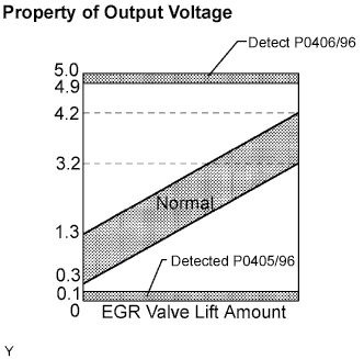
| Changes between 0.3 V and 4.2 V | Normal |
| Less than 0.1 V | P0405/96 (Low input voltage) |
| More than 4.9 V | P0406/96 (High input voltage) |
Tech Tips
The result values above are for when the ignition switch is ON (engine is stopped), or when the engine is fully warmed-up and idling.
MONITOR DESCRIPTION
When output voltage of the EGR valve position sensor deviates from the normal operating range of 0.1 to 4.9 V for more than 0.5 seconds, the ECM interprets this as a malfunction of the sensor circuit, and illuminates the MIL.
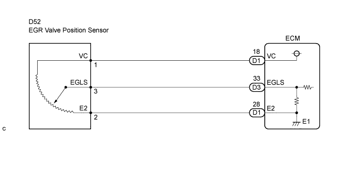
WIRING DIAGRAM
INSPECTION PROCEDURE
Note
After replacing the ECM, the new ECM needs registration Click here and initialization Click here.
Tech Tips
Read freeze frame data using the intelligent tester. The ECM records vehicle and driving condition information as freeze frame data the moment a DTC is stored. When troubleshooting, freeze frame data can help determine if the vehicle was running or stopped, if the engine was warmed up or not, and other data from the time the malfunction occurred.
PROCEDURE
-
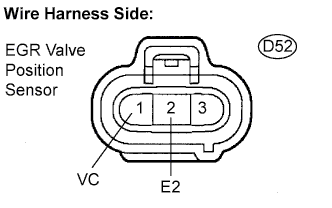
CHECK TERMINAL VOLTAGE (EGR VALVE POSITION SENSOR CONNECTOR)
-
Disconnect the D52 sensor connector.
-
Measure the voltage of the wire harness side connector.
Standard voltage Tester Connection Specified Condition D52-1 (VC) - D52-2 (D52) 4.5 to 5.5 V
NG 
CHECK HARNESS AND CONNECTOR (EGR VALVE POSITION SENSOR - ECM) Click here
OK 
-
-
INSPECT EGR VALVE POSITION SENSOR
-
Check the EGR valve position sensor. Click here
Standard resistance Tester connection EGR valve condition Spesified Condition D52-1 (VC) - D52-2 (E2) - 4 to 6 kΩ at 20°C (68°F) D52-3 (EGLS) - D52-2 (E2) Fully opened 3.9 kΩ at 20°C (68°F) D52-3 (EGLS) - D52-2 (E2) Fully closed 1.0 kΩ at 20°C (68°F)
NG 
REPLACE EGR VALVE ASSEMBLY
OK
-
-
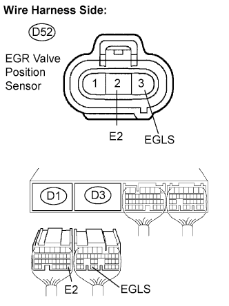
CHECK HARNESS AND CONNECTOR (EGR VALVE POSITION SENSOR - ECM)
-
Disconnect the D52 sensor connector.
-
Disconnect the D3 and D1 ECM connectors.
-
Measure the resistance of the wire harness side connectors.
Standard resistance Tester Connection Specified Condition D52-3 (EGLS) - D3-33 (EGLS) Below 1 Ω D52-2 (E2) - D1-28 (E2) Below 1 Ω D52-3 (EGLS) or D3-33 (EGLS) - Body ground 10 kΩ or higher D52-2 (E2) or D1-28 (E2) - Body ground 10 kΩ or higher
NG
REPAIR OR REPLACE HARNESS AND CONNECTOR
OK 
REPLACE ECM
-