ECD SYSTEM, Diagnostic DTC:P0110/24, P0112/24, P0113/24

| DTC Code | DTC Name |
|---|---|
| P0110/24 | Intake Air Temperature Circuit |
| P0112/24 | Intake Air Temperature Circuit Low Input |
| P0113/24 | Intake Air Temperature Circuit High Input |
DESCRIPTION
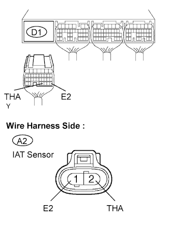
The Intake Air Temperature (IAT) sensor, mounted on the air cleaner hose, monitors the IAT.
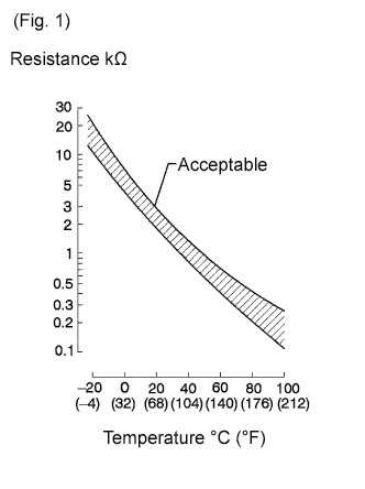
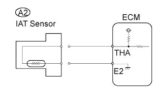
The IAT sensor has a thermistor that varies its resistance depending on the temperature of the intake air. When the air temperature is low, the resistance in the thermistor increases. When the temperature is high, the resistance decreases. The variations in resistance are communicated to the ECM as changes in voltage (see Fig. 1).
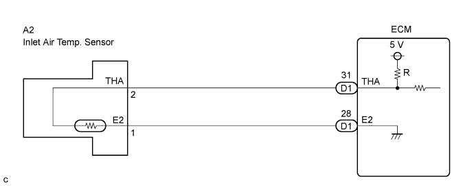
The IAT sensor is connected to the ECM (see below). The 5 V power source voltage in the ECM is applied to the IAT sensor from terminal THA via resistor R.
The resistor R and the IAT sensor are connected in series. When the resistance value of the IAT sensor changes in accordance with changes in the IAT, the voltage at terminal THA also changes. Based on this signal, the ECM increases the fuel injection volume to improve drive ability during cold engine operation.
| DTC No. | DTC Detection Condition | Trouble Area |
|---|---|---|
| P0110/24 | Open or short in IAT sensor circuit for 0.5 seconds (1 trip detection logic) |
|
| P0112/24 | Short in IAT sensor circuit for 0.5 seconds (1 trip detection logic) |
|
| P0113/24 | Open in IAT sensor circuit for 0.5 seconds (1 trip detection logic) |
|
Tech Tips
When DTC P0110/24, P0112/24 or P0113/24 is detected, check the intake air temperature by entering the following menus on the intelligent tester : Powertrain / Engine / Data List / Intake Air.
| Temperature Displayed | Malfunction |
|---|---|
| -40°C (-40°F) | Open circuit |
| 140°C (284°F) or more | Short circuit |
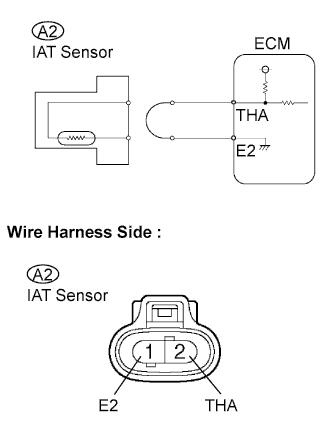
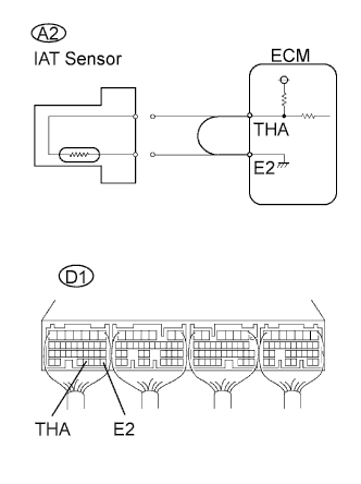
WIRING DIAGRAM
INSPECTION PROCEDURE
Note
After replacing the ECM, the new ECM needs registration Click here and initialization Click here.
Tech Tips
-
If DTCs related to different systems that have terminal E2 as the ground terminal are output simultaneously, terminal E2 may have an open circuit.
-
Read freeze frame data using the intelligent tester. The ECM records vehicle and driving condition information as freeze frame data the moment a DTC is stored. When troubleshooting, freeze frame data can help determine if the vehicle was running or stopped, if the engine was warmed up or not, and other data from the time the malfunction occurred.
When using intelligent tester:
PROCEDURE
-
READ VALUE USING INTAKE AIR TEMPERATURE SENSOR
-
Connect the intelligent tester to the DLC3.
-
Turn the ignition switch ON and turn the intelligent tester ON.
-
Enter the following menus: Powertrain / Engine / Data List / Intake Air.
-
Read the values.
OK Same value as the actual air temperature. Result Temperature Displayed Proceed to -40°C (-40°F) A 140°C (284°F) or more B OK (same as air temperature near intake manifold) C Tech Tips
-
If there is an open circuit, the intelligent tester indicates -40°C (-40°F).
-
If there is a short circuit, the intelligent tester indicates 140°C (284°F) or more.
-
B 
CHECK HARNESS AND CONNECTOR (SHORT IN WIRE HARNESS) Click here
C 
CHECK FOR INTERMITTENT PROBLEMS
A 
-
-
CHECK HARNESS AND CONNECTOR (OPEN IN WIRE HARNESS)
-
Disconnect the A2 IAT sensor connector.
-
Connect terminals 1 and 2 of the IAT sensor wire harness side connector.
-
Connect the intelligent tester to the DLC3.
-
Turn the ignition switch ON and turn the intelligent tester ON.
-
Enter the following menus: Powertrain / Engine / Data List / Intake Air.
-
Read the values.
OK 140°C (284°F) or more
OK
REPLACE INTAKE AIR TEMPERATURE SENSOR
NG
-
-
CHECK ECM (OPEN IN ECM)
-
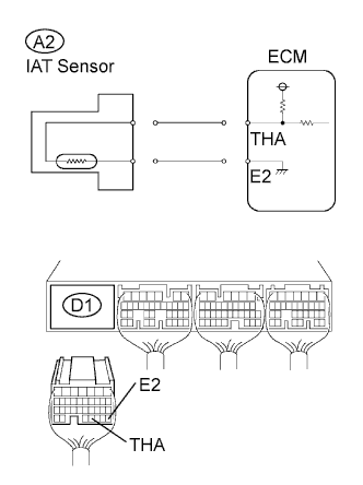
Disconnect the A2 IAT sensor connector.
-
Connect terminals THA and E2 of the D1 ECM connector.
Tech Tips
Before checking, perform a visual and contact pressure check on the ECM connector.
-
Connect the intelligent tester to the DLC3.
-
Turn the ignition switch ON and turn the intelligent tester ON.
-
Enter the following menus: Powertrain / Engine / Data List / Intake Air.
-
Read the values.
OK 140°C (284°F) or more
OK
REPAIR OR REPLACE HARNESS AND CONNECTOR
NG 
REPLACE ECM
-
-
CHECK HARNESS AND CONNECTOR (SHORT IN WIRE HARNESS)
-
Disconnect the A2 IAT sensor.
-
Connect the intelligent tester to the DLC3.
-
Turn the ignition switch ON and turn the intelligent tester ON.
-
Enter the following menus: Powertrain / Engine / Data List / Intake Air.
-
Read the values.
OK -40°C (-40°F)
OK
REPLACE INTAKE AIR TEMPERATURE SENSOR
NG
-
-
CHECK ECM (SHORT IN ECM)
-
Disconnect the A2 IAT sensor.
-
Disconnect the D1 ECM connector.
-
Connect the intelligent tester to the DLC3.
-
Turn the ignition switch ON and turn the intelligent tester ON.
-
Enter the following menus: Powertrain / Engine / Data List / Intake Air.
-
Read the values.
OK -40°C (-40°F)
OK
REPAIR OR REPLACE HARNESS AND CONNECTOR
NG
REPLACE ECM
-
When not using intelligent tester:
PROCEDURE
-
CHECK ECM TERMINAL VOLTAGE (THA TERMINAL)
-
Start engine.
-
Measure the voltage of the ECM connector.
Standard voltage Tester Connection Condition Specified Condition D1-31 (THA) - D1-28 (E2) Idling, IAT at 20°C (68°F) 0.5 to 3.4 V
OK
CHECK FOR INTERMITTENT PROBLEMS
NG
-
-
INSPECT INTAKE AIR TEMPERATURE SENSOR
-
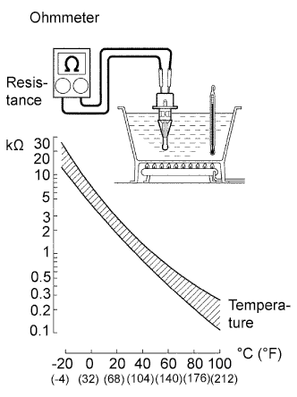
Remove the sensor.
-
Measure the resistance of the sensor.
Standard resistance Tester Connection Condition Specified Condition 1 - 2 20°C (68°F) 2.21 to 2.69 kΩ Note
When checking the IAT sensor in water, keep the terminals dry. After the check, wipe the sensor dry.
NG
REPLACE INTAKE AIR TEMPERATURE SENSOR
OK
-
-
CHECK HARNESS AND CONNECTOR (INTAKE AIR TEMPERATURE SENSOR - ECM)
-
Disconnect the D1 ECM connector.
-
Disconnect the A2 sensor connector.
-
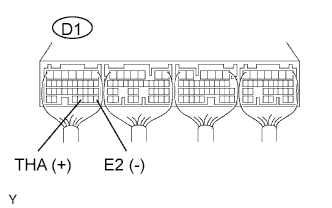
Measure the resistance of the wire harness side connectors.
Standard resistance Tester Connection Specified Condition D1-31 (THA) - A2-2 (THA) Below 1 Ω D1-28 (E2) - A2-1 (E2) Below 1 Ω D1-31 (THA) or A2-2 (THA) - Body ground 10 kΩ or higher D1-28 (E2) or A2-1 (E2) - Body ground 10 kΩ or higher
NG
REPAIR OR REPLACE HARNESS AND CONNECTOR
OK
REPLACE ECM
-