ECD SYSTEM, Diagnostic DTC:P0088/78, P1229/78

| DTC Code | DTC Name |
|---|---|
| P0088/78 | Fuel Rail / System Pressure - Too High |
| P1229/78 | Fuel Pump System |
DESCRIPTION
Refer to the system description Click here
| DTC No. | DTC Detection Condition | Trouble Area |
|---|---|---|
| P0088/78 | Internal fuel pressure of common rail is too high: Fuel pressure exceeds 200 MPa (2,039 kgf/cm2, 29,007 psi) (1 trip detection logic) |
|
| P1229/78 | Fuel over-feed: Internal fuel pressure continues exceeding target fuel pressure despite ECM closing suction control valve (1 trip detection logic) |
|
Tech Tips
-
DTC P0088/78 and P1229/78 are detected when drive the vehicle at 50 km/h (31 mph) for 5 minutes.
-
For more information on the supply pump (suction control valve) and common rail system, refer to the system description Click here.
-
If P0088/78 and/or P1229/78 is present, refer to the "Diagnostics Trouble Codes (DTCs) Table for Common Rail System" Click here.
-
When DTC P0088/78 and/or P1229/78 is set, check the internal fuel pressure of the common rail by entering the following menus on the intelligent tester : Powertrain / Engine / Data List / Fuel Press.
| Reference | ||||||
|---|---|---|---|---|---|---|
|
MONITOR DESCRIPTION
P0088/78 (Internal fuel pressure too high) :The ECM sets this DTC if the fuel pressure inside the common rail is more than 200 MPa (2,039 kgf/cm2, 29,007 psi). This DTC indicates that: 1) the suction control valve may be stuck open, 2) there may be an open or short in the suction control valve circuit.
If this DTC is set, the ECM enters fail-safe mode and limits the engine power. The fail-safe mode continues until the ignition switch is turned OFF.
P1229/78 (Fuel over-feed) :The ECM sets this DTC if the actual fuel pressure inside the common rail remains higher than the target fuel pressure, despite the ECM closing the suction control valve. This DTC indicates that the suction control valve may be stuck open, or there may be a short in its circuit. Under this condition, the pressure discharge valve operates frequently.
If this DTC is set, the ECM enters fail-safe mode and limits the engine power. The fail-safe mode continues until the ignition switch is turned OFF.
MONITOR STRATEGY
| Required sensor | Fuel pressure sensor |
|---|---|
| Frequency of operation | Continuous |
| Duration | 1 second |
| MIL operation | 1 driving cycle |
| Required sensor | Fuel pressure sensor |
|---|---|
| Frequency of operation | Continuous |
| Duration | 1 minute |
| MIL operation | 1 driving cycle |
TYPICAL ENABLING CONDITIONS
| Specification | |
|---|---|
| The monitor will not run if the fuel pressure sensor or suction control valve circuit is malfunctioning |
| Item | Specification |
|---|---|
| Target fuel pressure variation | Small |
| The monitor will not run if the fuel pressure sensor or suction control valve circuit is malfunctioning. | |
TYPICAL MALFUNCTION THRESHOLDS
| Detection Criteria | Threshold |
|---|---|
| Fuel pressure sensor | 200 MPa (2,039 kgf/cm2, 29,007 psi) or more |
| Detection Criteria | Threshold |
|---|---|
| The internal fuel pressure of the common rail when the suction control valve is closed. | Remains higher than target fuel pressure |
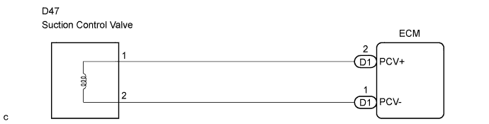
WIRING DIAGRAM
INSPECTION PROCEDURE
Note
-
After replacing the ECM, the new ECM needs registration Click here and initialization Click here.
-
After replacing the supply pump, the ECM needs initialization Click here.
Tech Tips
Read freeze frame data using the intelligent tester. The ECM records vehicle and driving condition information as freeze frame data the moment a DTC is stored. When troubleshooting, freeze frame data can help determine if the vehicle was running or stopped, if the engine was warmed up or not, and other data from the time the malfunction occurred.
PROCEDURE
-
CHECK OTHER DTC OUTPUT (IN ADDITION TO DTC P0088/78 AND/OR P1229/78)
-
Connect the intelligent tester to the DLC3.
-
Turn the ignition switch ON and turn the intelligent tester ON.
-
Enter the following menus: Powertrain / Engine / DTC.
-
Read the DTCs.
Result Display (DTC Output) Proceed to P0088/78 or P0088/78 and P1229/78 A P1229/78 B P0190/49, P0192/49 and/or P0193/49 C
B 
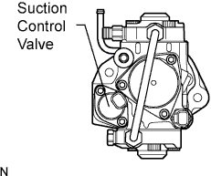
INSPECT SUPPLY PUMP ASSEMBLY (SUCTION CONTROL VALVE) Click here
C 
GO TO DTC CHART
A 
-
-
REPLACE COMMON RAIL ASSEMBLY
NEXT
-
INSPECT SUPPLY PUMP ASSEMBLY (SUCTION CONTROL VALVE)
-
Disconnect the D47 valve connector.
-
Measure the resistance of the suction control valve.
Standard resistance 1.9 to 2.3 Ω at 20°C (68°F)
NG
REPLACE SUCTION CONTROL VALVE
OK
-
-
CHECK IF DTC OUTPUT RECURS
-
Connect the intelligent tester to the DLC3.
-
Turn the ignition switch ON and turn the intelligent tester ON.
-
Enter the following menus: Powertrain / Engine / DTC / Clear.
-
Disconnect the suction control valve connector and then start the engine. Wait for 1 minute.
Tech Tips
If the engine does not start, the suction control valve is normal. Proceed to step 6.
-
Enter the following menus: Powertrain / Engine / DTC.
-
Read the DTCs.
Result Display (DTC Output) Proceed to No output A P1229/78 B
B
REPLACE SUCTION CONTROL VALVE
A
-
-
CHECK HARNESS AND CONNECTOR
-
Disconnect the D47 valve connector.
-
Disconnect the D1 ECM connector.
-
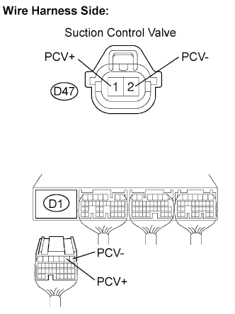
Measure the resistance of the wire harness side connectors.
Standard resistance Tester Connection Specified Condition D47-1 (PCV+) - D1-2 (PCV+) Below 1 Ω D47-2 (PCV-) - D1-1 (PCV-) Below 1 Ω D47-1 (PCV+) or D1-2 (PCV+) - Body ground 10 kΩ or higher D47-2 (PCV-) or D1-1 (PCV-) - Body ground 10 kΩ or higher
NG
REPAIR OR REPLACE HARNESS AND CONNECTOR
OK
-
-
CHECK ECM
-
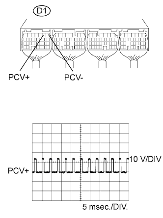
While cranking or idling the engine, check the waveform of the ECM connector using an oscilloscope.
Standard Tester Connection Specified Condition D1-2 (PCV+) - D1-1 (PCV-) Correct waveform shown Tool Setting 10 V/DIV., 5 msec./DIV. Condition Idling or cranking with warm engine Tech Tips
The waveform varies depending on the suction control valve operation.
NG
REPLACE ECM
OK 
END
-