ECD SYSTEM FREEZE FRAME DATA

-
DESCRIPTION
-
The ECM records vehicle and driving condition information as freeze frame data the moment a DTC is stored. When troubleshooting, freeze frame data can be helpful in determining whether the vehicle was moving or stationary, whether the air fuel ratio was lean or rich, as well as the other data recorded at the time of a malfunction.
Tech Tips
If it is impossible to duplicate the problem even though a DTC is stored, confirm the freeze frame data.
-
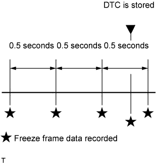
The ECM records engine conditions in the form of freeze frame data every 0.5 seconds. Using the GTS, 5 separate sets of freeze frame data can be checked.
-
3 data sets from before the DTC was stored
-
1 data set from when the DTC was stored
-
1 data set from after the DTC was stored
-
These data sets can be used to simulate the condition of the vehicle from around the time of the occurrence of the malfunction. The data may assist in identifying the cause of the malfunction, and in judging whether it was temporary or not.
-
-
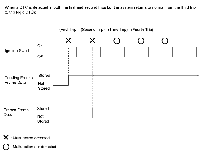
PENDING FREEZE FRAME DATA
Tech Tips
Pending freeze frame data is stored when a 2 trip DTC is first detected during the first trip.
-
Connect the GTS to the DLC3.
-
Turn the ignition switch on.
-
Turn the GTS on.
-
Enter the following menus: Engine and ECT / Trouble Codes.
-
Select a DTC in order to display its pending freeze frame data.
Tech Tips
-
Pending freeze frame data is cleared when any of the following occurs.
-
Using the GTS, the DTCs are cleared.
-
The cable is disconnected from the negative (-) auxiliary battery terminal.
-
40 trips with the engine fully warmed up have been performed after returning to normal.
(Pending freeze frame data will not be cleared by only returning the system to normal.)
-
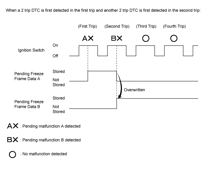
With previous pending freeze frame data stored, if pending freeze frame data is newly stored when a 2 trip DTC is detected in the first trip, the old freeze frame data will be replaced with the new one of the newly detected DTC in the next trip.
-
-
-
LIST OF FREEZE FRAME DATA
Tester Display Measurement Item Diagnostic Note Vehicle Speed Vehicle speed The speed indicated on the speedometer. Engine Speed Engine speed - Calculate Load Calculated load The load calculated by the ECM. Atmosphere Pressure Atmospheric pressure - MAP Absolute pressure inside intake manifold - Coolant Temp Engine coolant temperature If -40°C (-40°F), the sensor circuit is open.
If 140°C (284°F) or higher, the sensor circuit is shorted.
Intake Air Intake air temperature If -40°C (-40°F), the sensor circuit is open.
If 140°C (284°F) or higher, the sensor circuit is shorted.
Intake Air Temp (Turbo) Supported Intake air temp (turbo) Supported - Intake Air Temp (Turbo) Intake air temperature after intercooler If -40°C (-40°F), the sensor circuit is open.
If 190°C (374°F) or higher, the sensor circuit is shorted.
Engine Run Time Accumulated engine running time - Radiator Coolant Temp Engine coolant temperature (radiator side) If -40°C (-40°F), the sensor circuit is open.
If 190°C (374°F) or higher, the sensor circuit is shorted
Initial Engine Coolant Temp Engine coolant temperature at engine start - Initial Intake Air Temp Intake air temperature at engine start - Battery Voltage Battery voltage - Alternate Duty Ratio Alternate duty ratio - Glow Indicator Supported Glow indicator supported - Glow Indicator Glow indicator - Accel Position Accelerator pedal position sensor - Accel Sens. No.1 Volt % Accelerator pedal position No. 1 - Accel Sens. No.2 Volt % Accelerator pedal position No. 2 - Target Throttle Position Supported Target throttle position supported - Target Throttle Position Target throttle position - Target Throttle Position #2 Supported Target throttle position (bank 2) supported - Target Throttle Position #2 Target throttle position (bank 2) - Actual Throttle Position Supported Actual throttle position supported - Actual Throttle Position Actual throttle position - Actual Throttle Position #2 Supported Actual throttle position (bank 2) Supported - Actual Throttle Position #2 Actual throttle position (bank 2) - Throttle Motor DUTY Throttle actuator - Throttle Close Learning Value Throttle fully closed position learned value - Throttle Sensor Volt % Throttle position sensor output voltage - Injection Volume Injection volume - Inj. FB Vol. for Idle Injection feedback value for idle speed control - Inj Vol Feedback Learning Injection volume feedback learned value - Injection Feedback Val #1 Injection volume correction for cylinder 1 - Injection Feedback Val #2 Injection volume correction for cylinder 2 - Injection Feedback Val #3 Injection volume correction for cylinder 3 - Injection Feedback Val #4 Injection volume correction for cylinder 4 - Pilot 1 Injection Period Pilot 1 injection period - Pilot 2 Injection Period Pilot 2 injection period - Main Injection Period Main injection period - After Injection Period Post injection period - Pilot 1 Injection Timing Pilot 1 injection timing - Pilot 2 Injection Timing Pilot 2 injection timing - Main Injection Timing Main injection timing - After Injection Timing Post injection timing - Pilot Quantity Learning Pilot quantity learning status - Injector Pilot Quantity Learning Pilot quantity learning status - Actuator Pilot Quantity Learning Actuator pilot quantity learning status - Temperature Pilot Quantity Learning Temperature pilot quantity learning status - Catalyst Pilot Quantity Learning Catalyst pilot quantity learning status - Injection Pressure Correction Injection pressure feedback compensation volume - Injection EDU Relay Request Status of the EDU relay request - Target Common Rail Pressure Supported Target common rail pressure supported - Target Common Rail Pressure Target common rail pressure - Common Rail Pressure Supported Target common rail pressure supported - Common Rail Pressure Common rail pressure - Fuel Temperature Supported Fuel temperature supported - Fuel Temperature Fuel temperature - Target Pump SCV Current Final pump current target value - Pump SCV Learning Value Pump current learned value - Pump SCV Status Pump SCV status - Pump SCV Duty Request Pump SCV duty request - Target EGR Valve Pos Supported Target EGR valve position supported - Target EGR Valve Pos Target EGR valve position - Target EGR Pos. Target EGR valve position - Target EGR Valve Pos #2 Supported Target EGR valve position (bank 2) supported - Target EGR Valve Pos #2 Target EGR valve position (bank 2) - Actual EGR Valve Pos Supported Actual EGR valve position supported - Actual EGR Valve Pos. Actual EGR valve position - Actual EGR Valve Pos #2 Supported Actual EGR valve position (bank 2) supported - Actual EGR Valve Pos #2 Actual EGR valve position (bank 2) - EGR Position Sensor EGR valve position sensor - EGR Close Lrn. Val. EGR valve fully closed position learned value - EGR VSV VRV for EGR status - Starter Signal Starter signal - Neutral Position SW Signal Neutral position switch signal - Clutch Switch Clutch switch - Stop Light Switch Stop light switch - A/C Signal Air conditioning signal - Idle Up Signal Idle up signal status - Immobiliser Communication Immobiliser communication - TC Terminal TC terminal status - Time after DTC Cleared Cumulative time after DTC cleared - Distance from DTC Cleared Accumulated distance after DTC cleared - Warmup Cycle Cleared DTC Warmup cycles after DTC cleared - Dist Batt Cable Disconnect Distance driven after battery cable disconnected - TC and TE1 TC and TE1 terminals of DLC3 - Total Distance Traveled Total distance traveled - Brake Override System Brake override system - Communication with ECT Communication with ECT - Received MIL from ECT MIL status from ECT - Shift Position Sig from ECT Shift position from ECT - A/T Oil Temp from ECT ATF temperature from ECT - SPD (NO) Output shaft speed - ECT Lock Up ECT lock-up status -