ECD SYSTEM SYSTEM DESCRIPTION

-
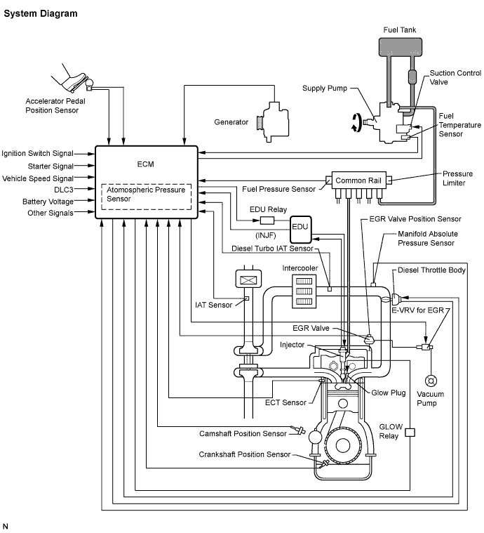
ENGINE CONTROL SYSTEM
-
COMMON RAIL SYSTEM DESCRIPTION
-
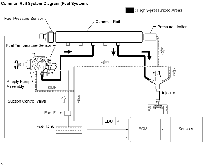
Common rail system:
The common rail system uses high-pressurized fuel for improved fuel economy and to provide robust engine power, while suppressing engine vibration and noise.
This system stores fuel, which has been pressurized and supplied by the supply pump, in the common rail. By storing fuel at high-pressure, the common rail system can provide fuel at stable fuel injection pressures, regardless of engine speed or engine load.
The ECM provides an electric current to the solenoid valve in the injector, using the EDU, to regulate the fuel injection timing and volume, and also monitors the internal fuel pressure of the common rail using the fuel pressure sensor. The ECM causes the supply pump to supply the fuel necessary to obtain the target fuel pressure.
In addition, this system uses the 2-Way Valve (TWV) inside the injector to open and close the fuel passage. Therefore, both fuel injection time and fuel injection volume can be precisely regulated by the ECM.
The common rail system provides two split fuel injections. In order to soften combustion shock, this system perform "spilot-injection" as the subsidiary fuel injection prior to the main fuel injection. This helps to reduce engine" vibration and noise.
-
Common rail system components:
Component Description Common rail Stores high-pressure fuel produced by supply pump Supply pump Operated by crankshaft
Supplies high-pressure fuel to common rail
Injector Injects fuel to combustion chamber based on signals from ECM Fuel pressure sensor Monitors internal fuel pressure of common rail and sends signals to ECM Pressure limiter Opens pressure limiter valve to reduce internal pressure in common rail when common rail pressure exceeds specified level Suction control valve Based on signals from ECM, adjusts fuel volume supplied to common rail and regulates internal fuel pressure -
Diagnostics trouble codes (DTCs) table for common rail system
Tech Tips
This table indicates typical DTC combinations for each malfunction occurrence.
Trouble Area Malfunction DTC No. Injector Open or short in injector circuit P0200/97, P0088/78* Injector Stuck open P0088/78 Injector Stuck closed - Fuel pressure sensor Open or short in fuel pressure sensor circuit or pressure sensor output fixed P0087/49, P0190/49, P0192/49, P0193/49 Pressure limiter Stuck open P0093/78 Pressure limiter Stuck closed P0088/78* Suction control valve Open or short in suction control valve circuit P0627/78, P1229/78, P0088/78* Suction control valve Stuck open P1229/78, P0088/78* Suction control valve Stuck closed - EDU Faulty EDU P0093/78*, P0200/97* Common rail system (Fuel system) Fuel leaks in high-pressure areas P0093/78 *: There may be no DTC output depending on condition of malfunction.
-
Diagnostics trouble code description for common rail system:
DTC No. Description P0087/49 Fuel pressure sensor output does not change P0088/78 Internal fuel pressure too high (200 MPa [2,039 kgf/cm2, 29,007 psi] or more)
P0093/78 Fuel leaks in high-pressure areas P0190/49 Open or short in fuel pressure sensor circuit (output voltage is too low or too high) P0192/49 Open or short in fuel pressure sensor circuit (output voltage is too low) P0193/49 Open or short in fuel pressure sensor circuit (output voltage is too high) P0200/97 Open or short in EDU or injector circuit P0627/78 Open or short in suction control valve circuit P1229/78 Fuel over-feed
-
-
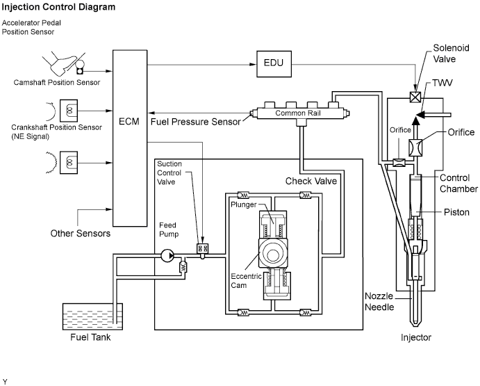
INJECTION CONTROL SYSTEM DESCRIPTION
The ECM controls the fuel injection system by using the injectors and supply pump. The ECM regulates the fuel injection volume and fuel injection timing by controlling both the duration and timing of energization to the solenoid valve in the injector. The ECM regulates injection pressure by controlling the suction control valve located in the supply pump.
The feed pump is used to pump fuel from the fuel tank to the supply pump.
-
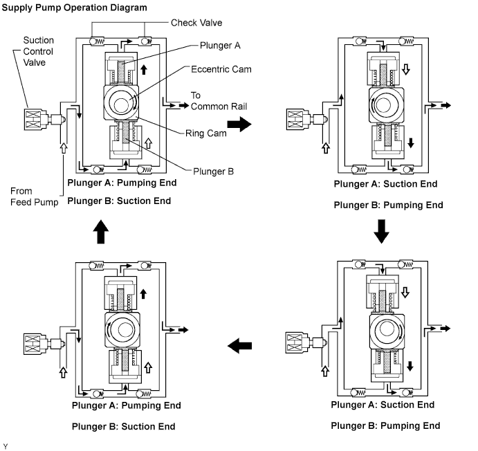
SUPPLY PUMP OPERATION SYSTEM DESCRIPTION
Supply the rotation of the eccentric cam causes the ring cam to push plunger A upward as illustrated below. The spring force pulls plunger B (located opposite plunger A) upward. As a result, plunger B draws the fuel in, and plunger A pumps fuel out at the same time.
-
SUCTION CONTROL VALVE OPERATION SYSTEM DESCRIPTION
Tech Tips
The ECM controls the suction control valve operation to regulate the fuel volume that is pumped by the supply pump to the common rail. This control is performed to adjust the internal fuel pressure of the common rail to the targeted injection pressure.
-
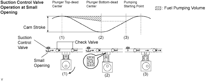
Small opening of the suction control valve:
-
When the opening of the suction control valve is small, the fuel suction path is kept narrow. Therefore the transferable fuel volume is reduced.
-
The suction volume becomes small due to the narrow path despite the plunger stroke being full. The difference between the geometrical volume and suction volume creates a vacuum.
-
Pumping will start at the time when the fuel pressure becomes higher than the common rail pressure.
-
-
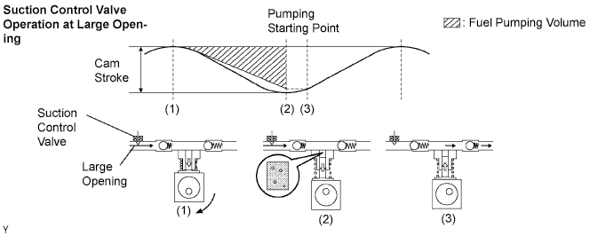
Large opening of the suction control valve:
-
When the opening of the suction control valve is large, the fuel suction path is kept wide. Therefore the transferable fuel volume is increased.
-
If the plunger stroke is full, the suction volume becomes large because of the wide path.
-
Pumping will start at the time when the fuel pressure becomes higher than the common rail pressure.
-
-