ECD SYSTEM, Diagnostic DTC:P0087/49, P0190/49, P0192/49, P0193/49

| DTC Code | DTC Name |
|---|---|
| P0087/49 | Fuel Rail / System Pressure - Too Low |
| P0190/49 | Fuel Rail Pressure Sensor Circuit |
| P0192/49 | Fuel Rail Pressure Sensor Circuit Low Input |
| P0193/49 | Fuel Rail Pressure Sensor Circuit High Input |
DESCRIPTION
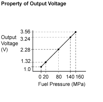
The ECM monitors the internal fuel pressure of the common rail using the fuel pressure sensor, and controls the suction control valve to regulate the internal pressure to the target pressure. The pressure sensor is a semiconductor that varies electrical resistance when applying pressure to its silicon chip. This sensor outputs the voltage in proportion to the internal fuel pressure.
| DTC No. | DTC Detection Condition | Trouble Area |
|---|---|---|
| P0087/49 | Fuel pressure sensor output voltage stays at fixed value (1 trip detection logic) |
|
| P0190/49 | Fuel pressure sensor output voltage is 0.55 V or less, or 4.9 V or more for 0.5 seconds (1 trip detection logic) |
|
| P0192/49 | Fuel pressure sensor output voltage is 0.55 V or less for 0.5 seconds (1 trip detection logic) |
|
| P0193/49 | Fuel pressure sensor output voltage is 4.9 V or more for 0.5 seconds (1 trip detection logic) |
|
Tech Tips
-
For more information on the fuel pressure sensor and common rail system, refer to the system description Click here.
-
If P0087/49, P0190/49, P0192/49 and/or P0193/49 is present, refer to the "Diagnostics Trouble Codes (DTCs) Table for Common Rail System" Click here.
-
When DTC P0087/49, P0190/49, P0192/49 and/or P0193/49 is set, check the internal fuel pressure of the common rail by entering the following menus on the intelligent tester : Powertrain / Engine / Data List / Fuel Press.
| Engine Speed | Fuel Pressure |
|---|---|
| Idling | Approximately 25 to 35 MPa |
| 3,000 rpm (No engine load) | Approximately 35 to 55 MPa |
MONITOR DESCRIPTION
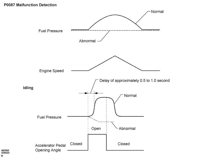
P0087/49 (Fuel pressure sensor output stays at fixed value) :Under normal condition, the internal fuel pressure of the common rail usually fluctuates 1 to 2 MPa (10 to 20 kgf/cm2, 145 to 290 psi) even when the driving condition is constant. The internal fuel pressure is approximately 25 to 35 MPa (255 to 357 kgf/cm2, 3,626 to 5,076 psi) when idling, and it increases to approximately 35 to 55 MPa (357 to 562 kgf/cm2, 5,076 to 7,991 psi) when running the engine at 3,000 rpm. This DTC is set if there is no fluctuation in the internal fuel pressure.
If this DTC is set, the ECM enters fail-safe mode and limits engine power. The fail-safe mode continues until the ignition switch is turned OFF.
These DTCs are set if the fuel pressure sensor output voltage is out of the standard range and an open or short malfunction of the sensor circuit has occurred.
If these DTCs are set, the ECM enters fail-safe mode and limits the engine power. The fail-safe mode continues until the ignition switch is turned OFF.
MONITOR STRATEGY
| Required Sensors | Fuel pressure sensor |
|---|---|
| Frequency of operation | Continuous |
| Duration | 1 second |
| MIL operation | 1 driving cycle |
| Required Sensors | Fuel pressure sensor |
|---|---|
| Frequency of operation | Continuous |
| Duration | 0.5 second |
| MIL operation | 1 driving cycle |
| Required Sensors | Fuel pressure sensor |
|---|---|
| Frequency of operation | Continuous |
| Duration | 0.5 second |
| MIL operation | 1 driving cycle |
| Required Sensors | Fuel pressure sensor |
|---|---|
| Frequency of operation | Continuous |
| Duration | 0.5 second |
| MIL operation | 1 driving cycle |
TYPICAL ENABLING CONDITIONS
| Item | Specification (Minimum) |
|---|---|
| Engine speed | 500 rpm |
| Battery voltage | 8 V |
| Fuel volume | 5 mm3 |
| The monitor will not run if the fuel pressure sensor circuit (P0190/49, P0192/49 and P0193/49) is malfunctioning | |
TYPICAL MALFUNCTION THRESHOLDS
| Detection Criteria | Threshold |
|---|---|
| Changing value of fuel pressure | Virtually no fluctuation |
| Detection Criteria | Threshold |
|---|---|
| Fuel pressure sensor output voltage | Less than 0.55 V or more than 4.9 V |
| Detection Criteria | Threshold |
|---|---|
| Fuel pressure sensor output voltage | Less than 0.55 V |
| Detection Criteria | Threshold |
|---|---|
| Fuel pressure sensor output voltage | More than 4.9 V |
WIRING DIAGRAM

INSPECTION PROCEDURE
Note
After replacing the ECM, the new ECM needs registration Click here and initialization Click here.
Tech Tips
-
After completing repairs, check that P0087/49, P0190/49, P0192/49 and/or P0193/49 is not set again.
-
If DTCs related to different systems that have terminal E2 as the ground terminal are output simultaneously, terminal E2 may have an open circuit.
-
Read freeze frame data using the intelligent tester. The ECM records vehicle and driving condition information as freeze frame data the moment a DTC is stored. When troubleshooting, freeze frame data can help determine if the vehicle was running or stopped, if the engine was warmed up or not, and other data from the time the malfunction occurred.
When using intelligent tester:
PROCEDURE
-
READ VALUE USING FUEL PRESSURE SENSOR
-
Connect the intelligent tester to the DLC3.
-
Start the engine and turn the intelligent tester ON.
-
Enter the following menus: Powertrain / Engine / Data List / Fuel Press.
-
Read the values.
OK The internal fuel pressure of the common rail is within the specification below. Engine Speed Fuel Pressure Idling Approximately 25 to 35 MPa 3,000 rpm (No engine load) Approximately 35 to 55 MPa
NG 
CHECK HARNESS AND CONNECTOR (ECM - FUEL PRESSURE SENSOR) Click here
OK 
-
-
CHECK IF DTC OUTPUT RECURS
-
Connect the intelligent tester to the DLC3.
-
Turn the ignition switch ON and turn the intelligent tester ON.
-
Enter the following menus: Powertrain / Engine / DTC / Clear.
-
Clear the DTC(s).
-
Let the engine idle for 60 seconds, and repeat quick engine RPM accelerations (to 2,500 rpm) for 30 seconds.
-
Enter the following menus: Powertrain / Engine / DTC.
-
Read the DTC(s).
Result Display (DTC Output) Proceed to P0087/49, P0190/49, P0192/49 or P0193/49 A No output B
B 
CHECK FOR INTERMITTENT PROBLEMS
A 
REPLACE ECM
-
-
CHECK HARNESS AND CONNECTOR (ECM - FUEL PRESSURE SENSOR)
-
Disconnect the D1 ECM connector.
-
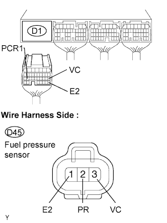
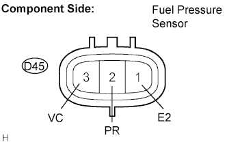
Disconnect the D45 sensor connector.
-
Measure the resistance of the wire harness side connectors.
Standard resistance Tester Connection Specified Condition D1-26 (PCR1) - D45-2 (PR) Below 1 Ω D1-18 (VC) - D45-3 (VC) Below 1 Ω D1-28 (E2) - D45-1 (E2) Below 1 Ω D1-26 (PCR1) or D45-2 (PR) - Body ground 10 kΩ or higher D1-18 (VC) or D45-3 (VC) - Body ground 10 kΩ or higher D1-28 (E2) or D45-1 (E2) - Body ground 10 kΩ or higher
NG
REPAIR OR REPLACE HARNESS AND CONNECTOR
OK
REPLACE COMMON RAIL ASSEMBLY
-
When not using intelligent tester:
PROCEDURE
-
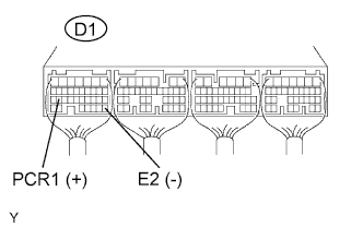
CHECK ECM TERMINAL VOLTAGE (PCR1 AND E2 TERMINALS)
-
Start the engine.
-
Measure the voltage of the ECM connector.
Standard voltage Tester Connection Condition Specified Condition D1-26 (PCR1) - D1-28 (E2) Idling 1.3 to 1.8 V
NG
CHECK COMMON RAIL ASSEMBLY (FUEL PRESSURE SENSOR) Click here
OK
REPLACE ECM
-
-
CHECK COMMON RAIL ASSEMBLY (FUEL PRESSURE SENSOR)
-
Disconnect the D45 sensor connector.
-
Measure the resistance of the sensor.
Standard resistance Tester Connection Specified Condition 1 (E2) - 2 (PR) 16.4 kΩ or less 2 (PR) - 3 (VC) 3 kΩ or less
NG
REPLACE COMMON RAIL ASSEMBLY
OK
-
-
CHECK HARNESS AND CONNECTOR (ECM - FUEL PRESSURE SENSOR)
-
Disconnect the D1 ECM connector.
-
Disconnect the D45 sensor connector.
-
Measure the resistance of the wire harness side connectors.
Standard resistance Tester Connection Specified Condition D1-26 (PCR1) - D45-2 (PR) Below 1 Ω D1-18 (VC) - D45-3 (VC) Below 1 Ω D1-28 (E2) - D45-1 (E2) Below 1 Ω D1-26 (PCR1) or D45-2 (PR) - Body ground 10 kΩ or higher D1-18 (VC) or D45-3 (VC) - Body ground 10 kΩ or higher D1-28 (E2) or D45-1 (E2) - Body ground 10 kΩ or higher Note
After replacing the ECM, the new ECM needs initialization Click here
NG
REPAIR OR REPLACE HARNESS AND CONNECTOR
OK
REPLACE ECM
-