ECD SYSTEM (w/o DPF) Turbocharger Oil Leak and White Smoke
DESCRIPTION
| Oil Leak Type | Description | Main Trouble Area |
|---|---|---|
| Internal oil leak (White smoke) |
Oil leak from bearing housing to compressor housing (intake side) or turbine housing (exhaust side) through seal rings. Internal oil leak is not visible from outside of turbocharger. If oil leak occurs from turbine side seal, large amount of white smoke will be emitted from exhaust pipe. |
|
| External oil leak | Oil leak from inside of turbocharger to outside of turbocharger (e.g. from FIPG seal, oil pipe flange or oil pipe union). Includes oil leak visible from outside of turbocharger. |
|
Tech Tips
-
Turbocharger oil leaks are classified into 2 types. One is an internal oil leak, and the other is an external oil leak.
-
When oil leaks and smoke occur, sometimes the turbocharger is mistakenly replaced, even though the turbocharger is not the cause of the problem.
-
When there are oil marks on the surface of the compressor housing, or oil in the compressor inlet or outlet, the problem may mistakenly be determined to be a turbocharger oil leak.
-
Each part of the turbocharger is shown below.
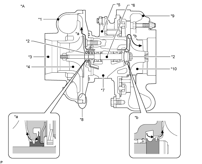
| *A | Variable Nozzle Type Turbocharger | - | - |
| *1 | Compressor Housing | *2 | Seal Ring |
| *3 | Compressor Inlet | *4 | Compressor Impeller |
| *5 | Bearing Housing | *6 | Turbine Shaft |
| *7 | Oil Drain (Outlet) | *8 | FIPG Sealing Part |
| *9 | Turbine Housing | *10 | Turbine Wheel |
| *a | Internal Oil Leak to Compressor Housing | *b | Internal Oil Leak to Turbine Housing |
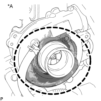
| *A |
Fig. 1 | - | - |
Tech Tips
-
Above illustration is an example.
-
If the oil stain is similar to the one shown in the illustration (fig. 1), it may be oil spray from parts surrounding the turbocharger or oil leaking from the air cleaner hose. Therefore, this kind of oil stain on the outer surface of the turbocharger is not an oil leak from the turbocharger (external oil leak), and is not related to white smoke. For identification of an actual turbocharger outer oil leak, check only the sealing part shown below.
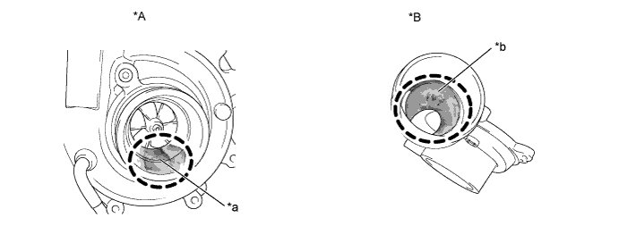
| *A | Fig. 2 | *B | Fig. 3 |
| *a | Oil Existence at Compressor Inlet (Max. 5 cm3) |
*b | Oil Existence at Compressor Outlet |
Tech Tips
-
Above illustration is an example.
-
A certain amount of oil is contained in the intake system because blow-by gas containing oil mist is returned to the intake system by the PCV. Therefore, the oil amount at the compressor inlet shown in the left figure (fig. 2) is normal and not an oil leak from the turbocharger (internal oil leak). Also, oil at the compressor outlet as shown in fig. 3 is normal.
In addition, the compressor impeller surface may blacken due to blow-by gas but this is not abnormal.
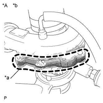
| *A | Fig. 4 | - | - |
| *a | In the case of an actual oil leak, oil leaks from the sealed part | *b | Oil Leak Check Point (FIPG Sealing Part) |
Tech Tips
-
Above illustration is an example.
-
This is an illustration (fig. 4) of an air leak test performed by applying soapy water to the area of the leak. Bubbles indicate the leak point.
-
Faults and Symptoms of Turbocharger Parts
Compressor Side Seal Ring Main fault Seal ring breakage Symptoms
-
Oil leak to compressor housing
-
Excessive oil consumption
Note
-
In case of compressor seal ring failure, large amount of oil would be found between compressor outlet and intercooler, and between intercooler and intake manifold, but not found at compressor inlet.
-
If large amount of oil is found at compressor inlet, it is not from turbocharger and may indicate a problem in the PCV system.
Turbine Side Seal Ring Main fault Seal ring breakage Symptoms
-
Oil leak to turbine housing
-
Large amount of white smoke from exhaust pipe
-
Excessive oil consumption
Note
-
In case of turbine seal ring failure, large amount of white smoke would be emitted continuously.
-
If white smoke is emitted only just after engine start (and it disappears later), or small amount of white smoke is emitted intermittently, it is not from turbocharger. It is due to failure of other parts.
-
If wet oil is found at turbine inlet, it is not from turbocharger. It is due to problem in other parts.
Bearing Housing (Oil Drain Clogging) Main fault Oil drain clogging by coked oil Symptoms Large amount of white smoke from exhaust pipe Tech Tips
-
Oil coking is caused by insufficient oil maintenance.
-
If the oil drain is clogged by coked oil, oil cannot be drained smoothly, and it overflows from the bearing housing to the compressor housing and turbine housing. This results in a large amount of white smoke from the exhaust pipe.
If any solid (coked oil) is visually confirmed inside the bearing housing, it can be assumed to be the cause of internal oil leak.
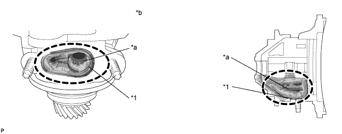
Text in Illustration *1 Oil Drain - - *a Coked Oil *b Oil Drain Clogged with Coked Oil Tech Tips
Above illustration is an example.
Turbine Shaft Main fault
-
Breakage
-
Seizure
Symptoms
-
Shaft does not rotate
-
Oil leak to compressor housing
-
Large amount of white smoke from exhaust pipe
-
Lack of power
-
Turbocharger noise changes
Note
-
In case of turbine shaft failure, lack of power due to lack of boost pressure will be felt.
-
In cold conditions, shaft rotation can feel somewhat clingy due to viscosity of oil. Be sure not to mistake it for unsmooth shaft rotation.
Compressor Impeller Main fault Breakage Symptoms
-
Shaft does not rotate
-
Oil leak to compressor housing
-
Lack of power
Note
-
In case of compressor impeller failure, large amount of oil would be found between compressor outlet and intercooler, and between intercooler and intake manifold, but not found at compressor inlet.
-
Oil is blocked by boost pressure at compressor seal ring. Therefore, if boost pressure does not increase due to breakage of compressor impeller, oil flows out to compressor housing.
Compressor Housing FIPG Sealing Part Symptoms Oil leak from FIPG sealing part Note
-
If oil stain is separated from FIPG sealing part, it can be determined to be due to oil spray from other parts surrounding turbocharger.
-
If oil stain is traced to hose connection part, it can be determined to be due to hose connection failure.
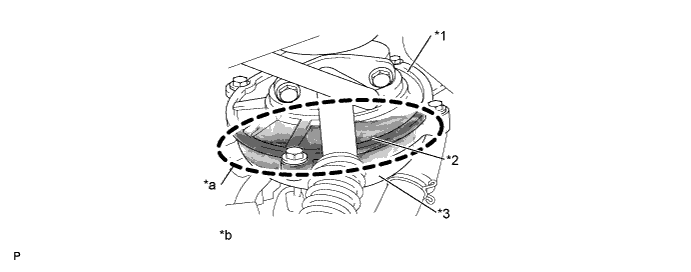
Text in Illustration *1 Compressor Back Plate *2 FIPG Sealing Part *3 Compressor Housing - - *a Oil Leak *b Oil Leak from FIPG Sealing Part Tech Tips
Above illustration is an example.
Intake Hoses Symptoms Oil leak from hose connection between hose and compressor housing Note If oil stain is traced to hose connection part, it can be determined to be due to hose connection failure. 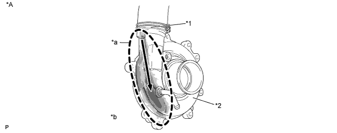
Text in Illustration *A Fig. 5 - - *1 Compressor Outlet *2 Compressor Housing *a Trace of Oil Leak from Hose Connection Part *b Oil Leak from Hose Connection Part Tech Tips
Above illustration is an example.
-
INSPECTION PROCEDURE
PROCEDURE
-
CHECK TYPE OF OIL LEAK
-
Check whether the oil leak is an internal or external oil leak.
Tech Tips
White smoke is not related to an external oil leak.
Oil Leak Type Description Internal oil leak
(White smoke)
Oil leak from bearing housing to compressor housing (intake side) or turbine housing (exhaust side) through seal rings.
Internal oil leak is not visible from outside of turbocharger.
If oil leak occurs from turbine side seal, large amount of white smoke will be emitted from exhaust pipe.
External oil leak Oil leak from inside of turbocharger to outside of turbocharger (e.g. from FIPG seal, oil pipe flange or oil pipe union).
Includes oil leaks visible from outside of turbocharger.
Result Result Proceed to External oil leak A Internal oil leak B
B 
CHECK WHETHER WHITE SMOKE IS EMITTED Click here
A 
-
-
REPLACE THE PART WHICH IS LEAKING OIL
-
Replace the part which is leaking oil.
NEXT 
END
-
-
CHECK WHETHER WHITE SMOKE IS EMITTED
-
Fully depress the accelerator pedal, and then release it.
-
Check whether white smoke is emitted or not when racing the engine.
CAUTION:
Be sure not to check for white smoke indoors.
Result Result Proceed to White smoke is emitted A White smoke is not emitted B
B
INSPECT COMPRESSOR INLET Click here
A
-
-
READ OUTPUT DTC (RELATED TO ENGINE)
-
Connect the intelligent tester to the DLC3.
-
Turn the ignition switch to ON and turn the tester ON.
-
Enter the following menus: Powertrain / Engine / DTC.
-
Read DTCs.
Result Result Proceed to No DTCs are output A DTCs related to engine are output B
B 
GO TO DTC CHART Click here
A
-
-
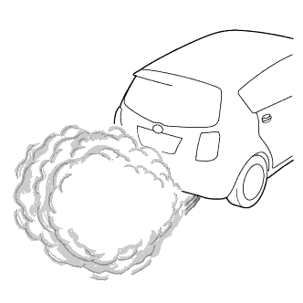
CHECK WHITE SMOKE (ACCORDING TO ENGINE CONDITION)
-
Check whether the white smoke is emitted only just after engine start and disappears later, or not.
Tech Tips
-
If white smoke appears for only a short period of time immediately after the engine is started, the white smoke is not from the turbocharger.
-
If the turbocharger is the cause of the problem, regardless of whether the engine is cold or warmed up, there will be a large amount of white smoke to the extent that visibility is obstructed for a few meters in the area of the smoke (as shown in the illustration).
-
Depending on whether there is oil mixed with the fuel, or whether there is unburned fuel present, the smell of the exhaust gas differs. When oil is mixed in, the exhaust gas smells like burning oil.
Result Result Proceed to Yes (white smoke is emitted only just after engine start) A No (white smoke is always and continuously emitted) B -
B
REPLACE TURBOCHARGER SUB-ASSEMBLY Click here
A
-
-
CHECK TEMPERATURE WHEN WHITE SMOKE IS EMITTED
-
Check whether the white smoke is emitted only in cold weather when the temperature is less than 0°C (32°F).
Tech Tips
-
If the white smoke is emitted only in cold conditions, the smoke is not from the turbocharger and may be the smoke of unburned fuel.
-
If misfiring occurs, unburned fuel is emitted.
Result Result Proceed to Yes (white smoke is emitted in only cold conditions) A No (white smoke is emitted in both cold and warm conditions) B -
B
CHECK INJECTOR COMPENSATION CODE Click here
A
-
-
INSPECT GLOW PLUG ASSEMBLY (RESISTANCE)
-
Inspect the glow plug assembly Click here.
NG
REPLACE GLOW PLUG ASSEMBLY Click here
OK
-
-
CHECK INJECTOR COMPENSATION CODE
-
Read the injector compensation codes Click here.
OK Compensation codes stored in the ECM match compensation codes of the installed fuel injectors. Tech Tips
If those do not match, register correct compensation code.
NG
REGISTER INJECTOR COMPENSATION CODE Click here
OK
-
-
CHECK FUEL SYSTEM (DIESEL INJECTION SYSTEM)
-
Check the fuel system Click here.
NG
REPAIR OR REPLACE FUEL SYSTEM
OK
-
-
CHECK ELECTRIC EGR CONTROL VALVE ASSEMBLY
Tech Tips
-
If the amount of EGR is excessive due to a failure of the EGR valve, combustion when the coolant temperature is cold becomes unstable and leads to misfire.
-
When the EGR valve cannot completely close, a lack of power is felt and the MAF sensor value deviates from the standard value.
-
Connect the intelligent tester to the DLC3.
-
Turn the ignition switch to ON and turn the tester ON.
-
Enter the following menus: Powertrain / Engine / Data List / EGR Close Lrn. Status.
-
Read the value.
OK EGR Close Lrn. Status is OK -
Start the engine and warm it up, and make sure the A/C switch and all accessory switches are off.
-
Turn the ignition switch OFF. Wait for 30 seconds, and then restart the engine.
-
Turn the tester ON.
-
Enter the following menus: Powertrain / Engine / Data List / MAF.
-
Read the MAF value displayed on the tester while the engine is idling.
-
Enter the following menus: Powertrain / Engine and ECT / Active Test / Activate the EGR Valve Close.
-
Read the MAF value when the EGR valve is closed using the Active Test function.
Tech Tips
-
If idling continues for 15 minutes or more, the EGR valve target opening angle becomes 0% (EGR valve fully closed). As this makes diagnosis impossible, it becomes necessary to drive the vehicle or to restart the engine.
-
Before performing the diagnosis, confirm that the EGR valve target opening angle is not 0%.
OK MAF value changes according to Active Test operation. Tech Tips
-
The problem may be a temporary one, due to the entry of deposits or foreign matter. Check that there are no deposits or foreign matter in the electric vacuum regulating valve assembly or mass air flow meter.
-
When Active Test is turned on and the MAF value does not change even though Actual EGR Valve Pos. or EGR Lift Sensor Volt % is changes, the EGR passages may be clogged.
-
-
Remove the electric EGR control valve assembly Click here.
-
Visually check the EGR valve for deposits. If there are deposits, clean the EGR valve and EGR passage (intake/exhaust manifold, EGR cooler, EGR pipes, etc.).
Note
-
When cleaning the EGR valve, make sure the valve is completely closed.
-
Do not forcibly open the valve, as it may be damaged or deformed.
-
When cleaning the EGR valve, use a piece of cloth soaked with cleaning solvent. Spraying the solvent directly onto these parts or soaking the parts in the solvent may damage the parts.
-
-
Hold the EGR valve up to a light, and visually check that there is no gap between the valve and body.
OK No light passes through (there is no gap between the valve and body). Tech Tips
-
If light passes through (there is a gap between the valve and body), replace the EGR valve assembly.
-
If any inspection result above is NG, check the EGR system, referring to the inspection procedure for DTC P0400.
-
NG
GO TO EGR SYSTEM INSPECTION PROCEDURE (DTC P0400) Click here
OK
-
-
CHECK CYLINDER COMPRESSION PRESSURE
-
Check the cylinder compression pressure Click here.
Tech Tips
-
If any of following malfunctions occurs, white smoke is emitted.
-
Nozzle seat sealing failure
-
Piston cracking
-
Piston rings breakage
-
To check whether the pistons and piston rings have a malfunction, remove the oil level dipstick. If oil sprays out, the pressure inside the crankcase has risen which indicates that there is a malfunction in a piston or piston ring.
-
NG
CHECK ENGINE TO DETERMINE CAUSE OF LOW COMPRESSION
OK
-
-
REPLACE TURBOCHARGER SUB-ASSEMBLY
-
Replace the turbocharger sub-assembly Click here.
NEXT
-
-
CONFIRM WHETHER MALFUNCTION HAS BEEN SUCCESSFULLY REPAIRED
-
Check whether the white smoke problem has been successfully repaired by starting the engine.
NEXT
END
-
-
INSPECT COMPRESSOR INLET
-
Remove the air cleaner hose from the compressor inlet (remove the compressor inlet elbow if necessary).
-
Check whether an excessive amount of oil is present or not, and whether excessive oil deposits are attached to the compressor impeller or not.
Tech Tips
-
A certain amount of oil may be present as shown in fig. 2 in "Description", because a certain amount of oil mist is contained in the PCV gas and this oil accumulates just before the compressor inlet.
-
If an excessive amount of oil is present at the compressor inlet, there may be a problem in the PCV system.
-
-
Reinstall the air cleaner hose (compressor inlet elbow).
NEXT
-
-
INSPECT COMPRESSOR OUTLET
-
Remove the air hose from the compressor outlet.
-
Check whether or not an excessive amount of oil or excessive oil deposits are present at the compressor outlet.
Tech Tips
A certain amount of oil may be present as shown in fig. 3 in "Description", because a certain amount of oil mist is contained in the PCV gas.
Result Result Proceed to Excessive amount of oil present at both compressor inlet and outlet C Excessive amount of oil present only at compressor outlet B Excessive amount of oil not present at compressor inlet and outlet A -
Reinstall the air hose.
B
REPLACE TURBOCHARGER SUB-ASSEMBLY Click here
C
CHECK PCV SYSTEM
A
-
-
INSPECT TURBINE INLET
-
Remove the turbocharger from the engine.
-
Check whether an excessive amount of wet oil or excessive oil deposits are present at the turbine inlet.
Tech Tips
Be sure not to mistake carbon soot for oil.
NEXT
-
-
INSPECT TURBINE OUTLET
-
Check whether an excessive amount of wet oil or excessive oil deposits are present at the turbine outlet.
Tech Tips
-
Be sure not to mistake carbon soot for oil.
-
If the turbocharger shaft is tilted, some amount of oil will flow out from the bearing housing. Therefore, be sure not to mistake oil that flowed out from the bearing housing during or after the removal of the turbocharger for oil that was present before the removal of the turbocharger.
-
If an excessive amount of oil or excessive oil deposits are present at the turbine inlet, this oil is coming from the exhaust port of the cylinders, and may indicate a problem in 1 or more cylinders.
Result Result Proceed to Excessive amount of oil present at both turbine inlet and outlet B Excessive amount of oil present only at turbine outlet A -
B
CHECK ENGINE TO DETERMINE CAUSE OF OIL IN TURBOCHARGER
A
-
-
REPLACE TURBOCHARGER SUB-ASSEMBLY
-
Replace the turbocharger sub-assembly Click here.
NEXT
-
-
CONFIRM WHETHER MALFUNCTION HAS BEEN SUCCESSFULLY REPAIRED
-
Check whether the oil leakage problem has been successfully repaired.
NEXT
END
-