ECD SYSTEM (w/o DPF), Diagnostic DTC:U0101

| DTC Code | DTC Name |
|---|---|
| U0101 | Lost Communication with TCM |
DESCRIPTION
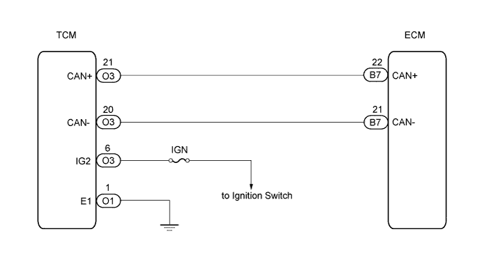
The ECM intercommunicates with the transmission control ECU through the Controller Area Network (CAN).
If there is a problem in this intercommunication, the ECM sets the DTC.
| DTC No. | DTC Detection Condition | Trouble Area |
|---|---|---|
| U0101 |
|
|
WIRING DIAGRAM
INSPECTION PROCEDURE
PROCEDURE
-
CHECK ANY OTHER DTCS OUTPUT (IN ADDITION TO DTC U0101)
-
Connect an intelligent tester to the DLC3.
-
Turn the ignition switch to ON and turn the tester ON.
-
Select the following menu items: powertrain / Engine / DTC.
-
Read DTCs.
Result Display (DTC Output) Proceed To U0101 A U0101 and other DTCs B Tech Tips
If any DTCs other than U0101 are output, troubleshoot those DTCs first.
B 
GO TO DTC CHART
A 
-
-
INSPECT TRANSMISSION CONTROL ECU
-
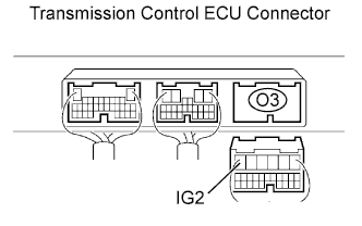
Disconnect the O3 transmission control ECU connector.
-
Turn the ignition switch to ON.
-
Measure the voltage of the wire harness side connector.
Standard voltage Tester Connection Specified Condition IG2 (O3-6) - Body ground 11 to 14 V -
Reconnect the transmission control ECU connector.
-
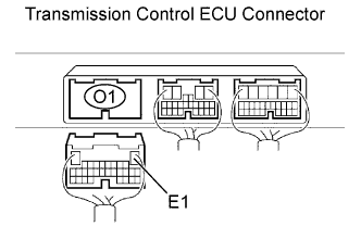
Disconnect the O1 transmission control ECU connector.
-
Check the resistance.
Standard resistance Tester Connection Specified Condition E1 (O1-1) - Body ground Below 1 Ω -
Reconnect the transmission control ECU connector.
NG
REPAIR OR REPLACE HARNESS OR CONNECTOR
OK
-
-
CHECK HARNESS AND CONNECTOR (TRANSMISSION CONTROL ECU - ECM)
-
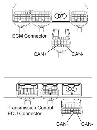
Disconnect the B7 ECM connector.
-
Disconnect the O3 transmission control ECU connector.
-
Check the resistance.
Standard resistance (Check for open) Tester Connection Specified Condition CAN+ (B7-22) - CAN+ (O3-21) Below 1 Ω CAN- (B7-21) - CAN- (O3-20) Below 1 Ω Standard resistance (Check for short) Tester Connection Specified Condition CAN+ (B7-22) or CAN+ (O3-21) - Body ground 10 kΩ or higher CAN- (B7-21) or CAN- (O3-20) - Body ground 10 kΩ or higher -
Reconnect the transmission control ECU connector.
-
Reconnect the ECM connector.
NG
REPAIR OR REPLACE HARNESS OR CONNECTOR
OK
-
-
REPLACE ECM
NEXT
-
CHECK WHETHER DTC OUTPUT RECURS (DTC U0101)
-
Connect an intelligent tester to the DLC3.
-
Turn the ignition switch to ON and turn the tester ON.
-
Select the following menu items: powertrain / Engine / DTC.
-
Read DTCs.
Result Display (DTC Output) Proceed To No output A U0101 B
B
REPLACE TRANSMISSION CONTROL ECU
A 
END
-