ECD SYSTEM (w/o DPF), Diagnostic DTC:P0047, P0048

| DTC Code | DTC Name |
|---|---|
| P0047 | Turbocharger/Supercharger Boost Control "A" Circuit Low |
| P0048 | Turbocharger/Supercharger Boost Control "A" Circuit High |
DESCRIPTION
Refer to DTC P0046 Click here.
| DTC No. | DTC Detection Condition | Trouble Area |
|---|---|---|
| P0047 | Both of following conditions met for 1 second or more (1 trip detection logic):
|
|
| P0048 | DC motor current 6.5 A or more for 0.5 seconds or more (1 trip detection logic) |
|
WIRING DIAGRAM
Refer to DTC P0046 Click here.
INSPECTION PROCEDURE
Tech Tips
Read freeze frame data using the intelligent tester. Freeze frame data records the engine condition when malfunctions are detected. When troubleshooting, freeze frame data can help determine if the vehicle was moving or stationary, if the engine was warmed up or not, and other data from the time the malfunction occurred.
PROCEDURE
-
PERFORM ACTIVE TEST USING INTELLIGENT TESTER (TEST THE TURBO CHARGER STEP MOTOR)
-
Turn the ignition switch to ON.
-
Turn the ignition switch off and check the DC motor operation (check the operation link movement).
OK When the ignition switch is turned off, the operation link moves as shown in A to D in the illustration below and the operation link contacts the stopper bolt 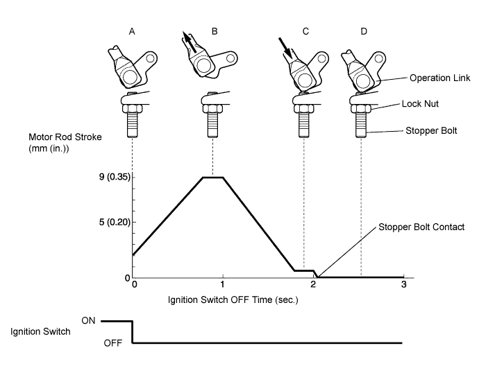
NG 
INSPECT TURBOCHARGER SUB-ASSEMBLY (DC MOTOR) Click here
OK 
CHECK FOR INTERMITTENT PROBLEMS
-
-
INSPECT TURBOCHARGER SUB-ASSEMBLY (DC MOTOR)
-
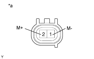
Text in Illustration *a Component with harness connected
(DC Motor)
Disconnect the D65 DC motor connector.
-
Measure the DC motor resistance.
Standard resistance 1 to 100 Ω
NG 
REPLACE TURBOCHARGER SUB-ASSEMBLY
OK 
-
-
CHECK HARNESS AND CONNECTOR (DC MOTOR - TURBO MOTOR DRIVER)
-
Disconnect the D65 DC motor connector.
-
Disconnect the B53 turbo motor driver connector.
-
Measure the resistance according to the value(s) in the table below.
Standard Resistance (Check for Open) Tester Connection Condition Specified Condition B53-12 (M+) - D65-2 (M+) Always Below 1 Ω B53-5 (M-) - D65-1 (M-) Always Below 1 Ω Standard Resistance (Check for Short) Tester Connection Condition Specified Condition B53-12 (M+) or D65-2 (M+) - Body ground Always 10 kΩ or higher B53-5 (M-) or D65-1 (M-) - Body ground Always 10 kΩ or higher -
Reconnect the turbo motor driver connector.
-
Reconnect the DC motor connector.
NG
REPAIR OR REPLACE HARNESS OR CONNECTOR
OK
-
-
REPLACE TURBO MOTOR DRIVER
-
Replace the turbo motor driver.
NEXT
-
-
CHECK WHETHER DTC OUTPUT RECURS (DTC P0047 AND/OR P0048)
-
Connect the intelligent tester to the DLC3.
-
Turn the ignition switch to ON and turn the tester on.
-
Clear the DTCs Click here.
-
Drive the vehicle with a city driving pattern at least 10 minutes.
-
Enter the following menus: Powertrain / Engine and ECT / DTC.
-
Read the DTCs.
Result Result Proceed to P0047 and/or P0048 is output A No DTC is output B
B
END
A
REPLACE TURBOCHARGER SUB-ASSEMBLY
-