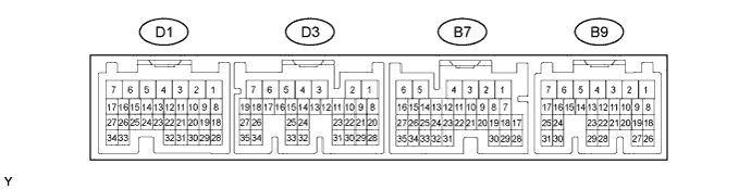
ECD SYSTEM (w/o DPF) TERMINALS OF ECM

Tech Tips
Each ECM terminal's standard voltage is shown in the table below.
In the table, first follow the information under "Condition". Look under "Symbols (Terminal No.)" for the terminals to be inspected. The standard voltage between the terminals is shown under "Specified Condition".
Use the illustration above as a reference for the ECM terminals.
| Symbols (Terminal No.) | Wiring Color | Terminal Description | Condition | Specified Condition |
|---|---|---|---|---|
| PCV+ (D1-2) - PCV- (D1-1) | P - Y-R | Suction control valve | Idling | Pulse generation (see waveform 1) |
| ALT (D1-8) - E1 (D3-7) | W - BR | Generator duty ratio | Idling | Pulse generation (see waveform 2) |
| VNTO (D1-10) - E1 (D3-7) | Y-G - BR | Turbo motor driver | Idling | Pulse generation (see waveform 3) |
| RFC2 (D1-11) - E1 (D3-7) | P-L - BR | No.2 cooling fan ECU | Ignition switch ON, fan operating | Pulse generation (See waveform 4) |
| RFC (D1-12) - E1 (D3-7) | LG-B - BR | No.1 cooling fan ECU | Ignition switch ON, fan operating | Pulse generation (See waveform 4) |
| FAN (D1-13) - E1 (D3-7) | W-L - BR | FAN3 relay (for No.3 cooling fan) | No.3 cooling fan operating | 0 to 3 V |
| No.3 cooling fan not operating | 11 to 14 V | |||
| SCV (D1-15) - E01 (D1-7) | W - BR | VSV for swirl control valve | Idling | 0 to 1.5 V |
| Engine speed 2600 rpm or more | 11 to 14 V | |||
| VNTI (D1-17) - E1 (D3-7) | Y-B - BR | Turbo motor driver | Idling | Pulse generation (see waveform 5) |
| VC (D1-18) - E2 (D1-28) | L-B - Y-R | Power source of sensor (specific voltage) | Ignition switch ON | 4.5 to 5.5 V |
| THW (D1-19) - E2 (D1-28) | R-W - Y-R | Engine coolant temperature sensor | Idling, engine coolant temperature 60 to 120°C (140 to 248°F) | 0.2 to 1.0 V |
| THIA (D1-20) - E2 (D1-28) | R-L - Y-R | Intake air temperature sensor (Diesel turbo IAT sensor) | Higher than atmospheric air temperature | 0.5 to 3.4 V |
| #4 (D1-21) - E1 (D3-7) | B-Y - BR | Injector | Idling | Pulse generation (see waveform 6) |
| #3 (D1-22) - E1 (D3-7) | Y-B - BR | |||
| #2 (D1-23) - E1 (D3-7) | G-Y - BR | |||
| #1 (D1-24) - E1 (D3-7) | G-R - BR | |||
| INJF (D1-25) - E1 (D3-7) | Y - BR | EDU | Idling | Pulse generation (see waveform 7) |
| PCR1 (D1-26) - E2 (D1-28) | P - Y-R | Common rail pressure sensor (main) | Idling, after warmed up | 1.7 to 2.2 V |
| NE+ (D1-27) - NE- (D1-34) | R - G | Crankshaft position sensor | Idling | Pulse generation (see waveform 8) |
| THF (D1-29) - E2 (D1-28) | R - Y-R | Fuel temperature sensor | Ignition switch ON | 0.5 to 3.4 V |
| THA (D1-31) - E2 (D1-28) | R - Y-R | IAT sensor (built into MAF meter) | Idling, intake air temperature 0 to 80°C (32 to 176°F) | 0.5 to 3.4 V |
| PRD (D1-32) - E1 (D3-7) | Y - BR | EDU | Ignition switch OFF | 4 to 6.5 V |
| PCR2 (D1-33) - E2 (D1-28) | G-R - Y-R | Common rail pressure sensor (sub) | Idling, after warmed up | 1.2 to 1.6 V |
| VCS (D3-2) - E2S (D3-1) | G-B - G | Power source of fuel pressure sensor (sub) | Ignition switch ON | 4.5 to 5.5 V |
| LUSL (D3-4) - E1 (D3-7) | B - BR | Diesel throttle motor duty signal | Engine warmed up, racing engine | Pulse generation (see waveform 9) |
| EGR (D3-9) - E1 (D3-7) | B-W - BR | E-VRV for EGR | Ignition switch ON | Pulse generation (see waveform 10) |
| EGRC (D3-18) - E1 (D3-7) | W-L - BR | VSV for EGR Cut | Ignition switch ON, EGR cuts (accelerator pedal fully depressed) | 0 to 1.5 V |
| G+ (D3-23) - G- (D3-31) | R - G | Camshaft position sensor | Idling | Pulse generation (see waveform 8) |
| VG (D3-24) - EVG (D3-32) | B-L - B | MAF meter | Idling, A/C switch OFF | 0.2 to 3.1 V |
| PIM (D3-28) - E2 (D1-28) | P - Y-R | Manifold absolute pressure sensor | Apply negative pressure of 40 kPa (300 mmHg, 11.8 in.Hg) | 0.1 to 0.7 V |
| Same as atmospheric pressure | 0.8 to 1.5 V | |||
| Apply positive pressure of 170 kPa (1,275 mmHg, 50.2 in.Hg) | 1.6 to 2.3 V | |||
| VLU (D3-29) - E2 (D1-28) | R-L - Y-R | Throttle position sensor | Ignition switch ON, throttle valve fully opened |
3.6 to 4.2 V |
| Ignition switch ON, throttle valve fully closed |
0.4 to 1.0 V | |||
| EGLS (D3-33) - E1 (D3-7) | P - BR | EGR valve position sensor | Ignition switch ON | 0.6 to 1.4 V |
| Idling | 1.9 to 2.9 V | |||
| BATT (B7-2) - E1 (D3-7) | B-R - BR | Battery (for measuring the battery voltage and for the ECM memory) | Always | 11 to 14 V |
| ST1- (B7-14) - E1 (D3-7) | R-L - BR | Stop light switch (opposite to STP) |
Ignition switch ON, brake pedal depressed | 0 to 1.5 V |
| Ignition switch ON, brake pedal released | 7.5 to 14 V | |||
| STP (B7-15) - E1 (D3-7) | R-W - BR | Stop light switch | Ignition switch ON, brake pedal depressed | 7.5 to 14 V |
| Ignition switch ON, brake pedal released | 0 to 1.5 V | |||
| SPD (B7-17) - E1 (D3-7) | P-L - BR | Speed signal from combination meter | Ignition switch ON, slowly rotate wheel | Pulse generation (see waveform 11) |
| CAN- (B7-21) - E1 (D3-7) | W - BR | CAN communication line | Ignition switch ON | Pulse generation (see waveform 12) |
| CAN+ (B7-22) - E1 (D3-7) | L - BR | CAN communication line | Ignition switch ON | Pulse generation (see waveform 13) |
| CANL (B7-23) - E1 (D3-7) | W - BR | CAN communication line | During transmission | Pulse generation (See waveform 12) |
| CANH (B7-24) - E1 (D3-7) | B - BR | CAN communication line | During transmission | Pulse generation (See waveform 13) |
| +B (B9-1) - E1 (D3-7) | B-R - BR | Power source of ECM | Ignition switch ON | 11 to 14 V |
| THWO (B9-2) - E1 (D3-7) | Y - BR | Engine coolant temperature signal for combination meter | Ignition switch ON | Pulse generation (See waveform 14) |
| TACH (B9-4) - E1 (D3-7) | B-Y - BR | Engine speed | Idling | Pulse generation (see waveform 15) |
| NSW (B9-6) - E1 (D3-7) | B-W - BR | Park neutral switch signal | IG switch ON and shift lever P and N position | Below 2 V |
| IG switch ON and shift lever except P and N position | 11 to 14 V | |||
| STA (B9-7) - E1 (D3-7) | R - BR | Starter signal | Cranking | 6.0 V or higher |
| MREL (B9-8) - E1 (D3-7) | G-Y - BR | MAIN relay | Ignition switch ON | 11 to 14 V |
| 10 seconds elapsed after ignition switch OFF | 0 to 1.5 V | |||
| IGSW (B9-9) - E1 (D3-7) | B-R - BR | Ignition switch | Ignition switch ON | 11 to 14 V |
| IREL (B9-10) - E1 (D3-7) | R-L - BR | EDU relay | Ignition switch ON | 0 to 1.5 V |
| TC (B9-11) - E1 (D3-7) | P - BR | Terminal TC of DLC3 | Ignition switch ON | 11 to 14 V |
| W (B9-12) - E1 (D3-7) | G-R - BR | MIL | MIL illuminated | 0 to 3 V |
| MIL not illuminated | 11 to 14 V | |||
| GIND (B9-14) - E1 (D3-7) | B-W - BR | Glow indicator light | Glow indicator light illuminated soon after ignition switch turned ON | Below 3 V |
| Idling | 11 to 14 V | |||
| GREL (B9-15) - E1 (D3-7) | G - BR | GLOW relay | Cranking | 11 to 14 V |
| 10 minutes after engine started | 0 to 1.5 V | |||
| RTHW (B9-20) - E2 (D1-28) | L-R - Y-R | Engine coolant temperature sensor (for radiator) | Idling, radiator side engine coolant temperature -20 to 80°C (-4 to 176°F) | 0.5 to 4.5 V |
| VPA (B9-22) - EPA (B9-28) | L - W-L | Accelerator pedal position sensor (for engine control) | Ignition switch ON, accelerator pedal fully released | 0.5 to 1.1 V |
| Ignition switch ON, accelerator pedal fully depressed | 2.6 to 4.5 V | |||
| VPA2 (B9-23) - EPA2 (B9-29) | B - W-R | Accelerator pedal position sensor (for sensor malfunction detection) | Ignition switch ON, accelerator pedal fully released | 1.2 to 2.0 V |
| Ignition switch ON, accelerator pedal fully depressed | 3.4 to 5.0 V | |||
| VCPA (B9-26) - EPA (B9-28) | W - W-L | Power source of accelerator pedal position sensor (for VPA) | Ignition switch ON | 4.5 to 5.5 V |
| VCP2 (B9-27) - EPA2 (B9-29) | R-L - W-R | Power source of accelerator pedal position sensor (for VPA2) | Ignition switch ON | 4.5 to 5.5 V |
| E02 (D1-6) - Body ground | BR - Body ground | Ground | Always | Below 1 Ω |
| E01 (D1-7) - Body ground | BR - Body ground | |||
| E2 (D1-28) - Body ground | Y-R - Body ground | |||
| E1 (D3-7) - Body ground | BR - Body ground | |||
| EC (B7-6) - Body ground | W-B - Body ground | |||
| E0M (B9-16) - Body ground | W-B - Body ground |
-
WAVEFORM 1
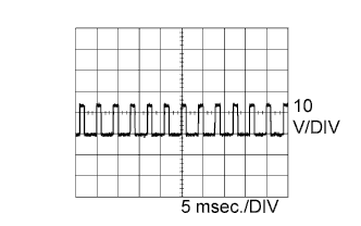
Suction control valve signal ECM Terminal Name Between PCV+ and PCV- Tester Range 10 V/DIV, 5 msec./DIV Condition Idling or cranking with warm engine Tech Tips
The waveform varies depending on the suction control valve operation.
-
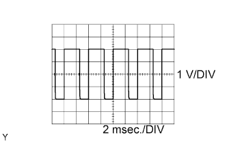
WAVEFORM 2
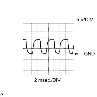
Generator duty ratio signal ECM Terminal Name Between ALT and E1 Tester Range 5 V/DIV, 2 msec./DIV Condition Idling Tech Tips
The wavelength becomes shorter as the engine rpm increases.
-
WAVEFORM 3
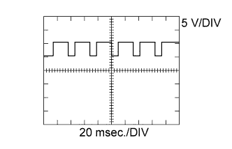
Turbo motor driver input signal ECM Terminal Name Between VNTO and E1 Tester Range 5 V/DIV, 20 msec./DIV Condition Idling with warm engine Tech Tips
The waveform varies depending on the turbocharger operation.
-
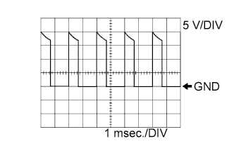
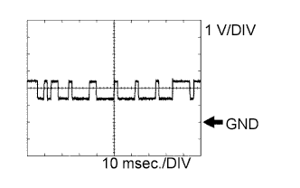
WAVEFORM 4
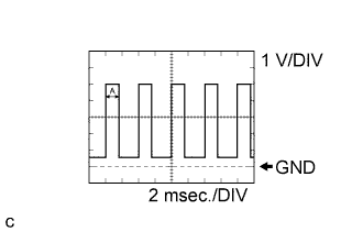
Cooling fan signal ECM Terminal Name Between RFC and E1
Between RFC2 and E1
Tester Range 1 V/DIV, 2 msec./DIV Condition Idling with warm engine, fan operating Tech Tips
Waveform time A changes according to coolant temperature.
-
WAVEFORM 5
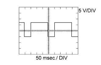
Turbo motor driver output signal ECM Terminal Name Between VNTI and E1 Tester Range 5 V/DIV, 50 msec./DIV Condition Idling with warm engine Tech Tips
The waveform varies depending on the turbocharger status.
-
WAVEFORM 6
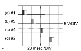
No. 1 (to No. 4) Injector injection signal ECM Terminal Name (a) Between #1 and E1
(b) Between #3 and E1
(c) Between #4 and E1
(d) Between #2 and E1
Tester Range 5 V/DIV, 20 msec./DIV Condition Idling with warm engine Tech Tips
The waveform varies depending on the injector injection.
-
WAVEFORM 7
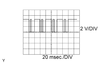
Injector injection confirmation signal ECM Terminal Name Between INJF and E1 Tester Range 2 V/DIV, 20 msec./DIV Condition Idling with warm engine Tech Tips
The waveform varies depending on the injector injection.
-
WAVEFORM 8
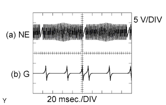
Crankshaft position sensor signal and Camshaft position sensor signal ECM Terminal Name (a) Between NE+ and NE-
(b) Between G+ and G-
Tester Range 5 V/DIV, 20 msec./DIV Condition Idling with warm engine Tech Tips
The waveform varies depending on the engine speed.
-
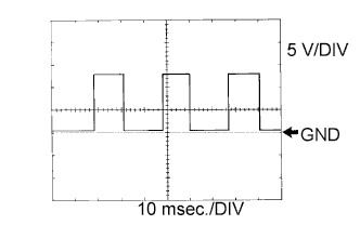
WAVEFORM 9
Diesel throttle motor signal ECM Terminal Name Between LUSL and E1 Tester Range 1 V/DIV, 2 msec./DIV Condition Warm engine with racing engine Tech Tips
The waveform varies depending on the throttle valve operation.
-
WAVEFORM 10
E-VRV for EGR signal ECM Terminal Name Between EGR and E1 Tester Range 5 V/DIV, 1 msec./DIV Condition Idling with warm engine Tech Tips
The waveform varies depending on the E-VRV (for E-EGR) operation.
-
WAVEFORM 11
Vehicle speed signal ECM Terminal Name Between SPD and E1 Tester Range 5 V/DIV, 10 msec./DIV Condition Driving at vehicle speed of 40 km/h (25 mph) Tech Tips
The wavelength becomes shorter as the vehicle speed increases.
-
WAVEFORM 12
CAN communication signal ECM Terminal Name Between CAN- and E1
Between CANL and E1
Tester Range 1 V/DIV, 10 msec./DIV Condition Engine is stopped, ignition switch ON Tech Tips
The waveform varies depending on the CAN communication signal.
-
WAVEFORM 13
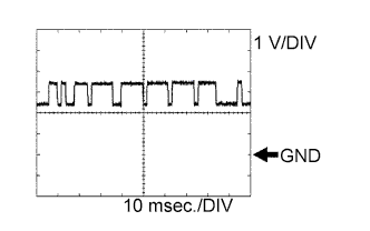
CAN communication signal ECM Terminal Name Between CAN+ and E1
Between CANH and E1
Tester Range 1 V/DIV, 10 msec./DIV Condition Engine is stopped, ignition switch ON Tech Tips
The waveform varies depending on the CAN communication signal.
-
WAVEFORM 14
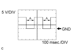
Engine coolant temperature signal for combination meter ECM Terminal Name Between THWO and E1 Tester Range 5 V/DIV, 100 msec./DIV Condition Idling Tech Tips
Waveform time A changes according to coolant temperature.
-
WAVEFORM 15
Engine speed signal ECM Terminal Name Between TACH and E1 Tester Range 5 V/DIV, 10 msec./DIV Condition Idling Tech Tips
The wavelength becomes shorter as the engine rpm increases.