ECD SYSTEM (w/ DPF), Diagnostic DTC:U0101

| DTC Code | DTC Name |
|---|---|
| U0101 | Lost Communication with TCM |
DESCRIPTION
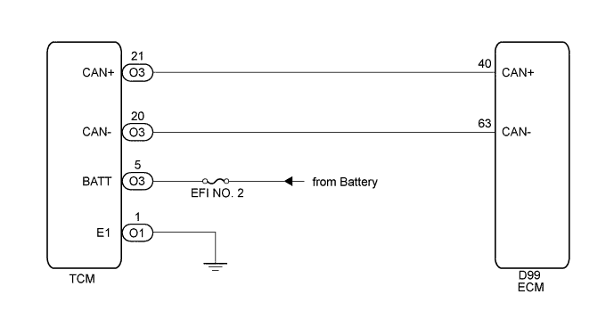
The ECM (engine control unit) communicates with the TCM (transmission control ECU) through the Controller Area Network (CAN).
If there is a problem with this communication, the ECM stores a DTC.
| DTC Detection Drive Pattern | DTC Detection Condition | Trouble Area |
|---|---|---|
| Ignition switch ON for 3 seconds | Both conditions are met for 1.25 seconds (1 trip detection logic):
|
|
WIRING DIAGRAM
INSPECTION PROCEDURE
Note
-
Inspect the fuses of circuits related to this system before performing the following inspection procedure.
-
After replacing the ECM, the new ECM needs registration Click here and initialization Click here.
-
After replacing the fuel supply pump assembly, the ECM needs initialization Click here.
-
After replacing an injector assembly, the ECM needs registration Click here.
Tech Tips
Read freeze frame data using the GTS. Freeze frame data records the engine condition when malfunctions are detected. When troubleshooting, freeze frame data can help determine if the vehicle was moving or stationary, if the engine was warmed up or not, and other data from the time the malfunction occurred.
PROCEDURE
-
CHECK FOR ANY OTHER DTCS OUTPUT (IN ADDITION TO DTC U0101)
-
Connect the GTS to the DLC3.
-
Turn the ignition switch to ON and turn the GTS on.
-
Enter the following menus: Powertrain / Engine and ECT / Trouble Codes.
-
Read the DTCs.
Result Result Proceed to U0101 is output A U0101 and other DTCs are output B Tech Tips
If any DTCs other than U0101 are output, troubleshoot those DTCs first.
B 
GO TO DTC CHART Click here
A 
-
-
INSPECT TCM POWER SOURCE CIRCUIT (POWER SOURCE AND BODY GROUND)
-
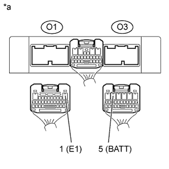
Text in Illustration *a Rear view of wire harness connector
(to TCM)
Disconnect the TCM connector.
-
Measure the voltage according to the value(s) in the table below.
Standard Voltage Tester Connection Switch Condition Specified Condition O3-5 (BATT) - O1-1 (E1) Ignition switch ON 11 to 14 V -
Reconnect the TCM connector.
NG
REPAIR OR REPLACE HARNESS OR CONNECTOR
OK
-
-
CHECK HARNESS AND CONNECTOR (ECM - TCM)
-
Disconnect the TCM connector.
-
Disconnect the ECM connector.
-
Measure the resistance according to the value(s) in the table below.
Standard Resistance Tester Connection Condition Specified Condition D99-40 (CAN+) - O3-21 (CAN+) Always Below 1 Ω D99-63 (CAN-) - O3-20 (CAN-) Always Below 1 Ω D99-40 (CAN+) or O3-21 (CAN+) - Body ground or other terminals Always 1 MΩ or higher D99-63 (CAN-) or O3-20 (CAN-) - Body ground or other terminals Always 1 MΩ or higher -
Reconnect the TCM connector.
-
Reconnect the ECM connector.
NG
REPAIR OR REPLACE HARNESS OR CONNECTOR
OK
-
-
REPLACE ECM
-
Replace the ECM Click here.
NEXT
-
-
CHECK WHETHER DTC OUTPUT RECURS (DTC U0101)
-
Connect the GTS to the DLC3.
-
Turn the ignition switch to ON and turn the GTS on.
-
Enter the following menus: Powertrain / Engine and ECT / Trouble Codes.
-
Read the DTCs.
Result Result Proceed to No DTC is output A U0101 is output B
B
REPLACE TCM
A 
END
-