ECD SYSTEM (w/ DPF), Diagnostic DTC:P20CF

| DTC Code | DTC Name |
|---|---|
| P20CF | Exhaust Aftertreatment Fuel Injector "A" Stuck Open |
DESCRIPTION
Refer to DTC P200C Click here.
| DTC Detection Drive Pattern | DTC Detection Condition | Trouble Area |
|---|---|---|
| PM forced regeneration | AF Lambda B1S1 is less than 0.85 for a certain time while the engine is running (1 trip detection logic) |
Common Inspection Item: |
| DTC No. | Data List |
|---|---|
| P20CF | AF Lambda B1S1 Exhaust Temperature B1S2 Exhaust Temperature B1S3 |
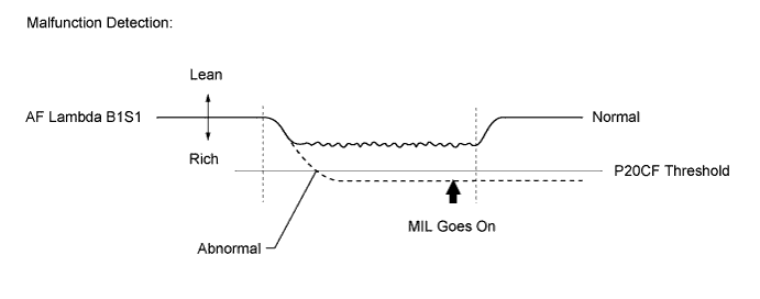
MONITOR DESCRIPTION
The ECM monitors the air fuel ratio to detect whether the exhaust fuel addition injector assembly is stuck open.
If the air fuel ratio becomes too rich, the ECM determines that the exhaust fuel addition injector assembly is stuck open, illuminates the MIL and limits engine output.
INSPECTION PROCEDURE
Note
-
Inspect the fuses of circuits related to this system before performing the following inspection procedure.
-
After replacing the ECM, the new ECM needs registration Click here and initialization Click here.
-
After replacing the fuel supply pump assembly, the ECM needs initialization Click here.
-
After replacing an injector assembly, the ECM needs registration Click here.
Tech Tips
Read freeze frame data using the intelligent tester. Freeze frame data records the engine condition when malfunctions are detected. When troubleshooting, freeze frame data can help determine if the vehicle was moving or stationary, if the engine was warmed up or not, and other data from the time the malfunction occurred.
PROCEDURE
-
CHECK DTC OUTPUT (IN ADDITION TO DTC P20CF)
-
Connect the intelligent tester to the DLC3.
-
Turn the ignition switch to ON.
-
Turn the tester on.
-
Enter the following menus: Powertrain / Engine and ECT / DTC.
-
Read the DTCs.
Result Result Proceed to P20CF is output A P20CF and other DTCs are output B Tech Tips
-
When DTC P20CF and following DTCs are output, uncombusted fuel adhesion to the air fuel ratio sensor due to air fuel ratio sensor malfunction, fuel leaks, insufficient combustion due to parts malfunction (intake, exhaust or injection system), or an exhaust fuel addition injector assembly wiring malfunction is suspected as a cause. Therefore, diagnose the following DTCs first.
-
DTCs for the air fuel ratio sensor are P2237, P2238, P2239, P2252 and P2253 Click here.
-
A DTC for fuel leakage is P0093 Click here.
-
DTCs for the exhaust fuel addition injector assembly wiring malfunction are P20CB, P20CD and P20CE Click here.
-
A DTC for EGR valve flow malfunction is P0400 Click here.
-
A DTC for EGR valve stuck open is P042E Click here.
-
B 
GO TO DTC CHART Click here
A 
-
-
CHECK FOR WHITE SMOKE (WHITE SMOKE AND ODOR)
Note
If a fuel odor is noted from the white smoke has during the inspection, fuel leaks from the exhaust fuel addition injector assembly are suspected.
-
Disconnect the cable from the negative (-) battery terminal or remove the ECD fuse for 1 minute or more.
-
Start the engine and race it to 3000 rpm several times.
-
Check for white smoke in the exhaust gas. If found, check for a fuel odor or the smell of burning oil.
Result Result Proceed to White smoke and a fuel odor are present. A White smoke and a smell of burning oil are present. B Except above C
B
CHECK AND REPLACE TURBOCHARGER SUB-ASSEMBLY Click here
C
CHECK FUEL INJECTION SYSTEM Click here
A
-
-
PERFORM CONFIRMATION DRIVING PATTERN (WHITE SMOKE AND SENSOR INSPECTION)
-
Connect the intelligent tester to the DLC3.
-
Turn the ignition switch to ON.
-
Turn the tester on.
-
Enter the following menus: Powertrain / Engine and ECT / Data List / AF Lambda B1S1 and Exhaust Temperature B1S3.
-
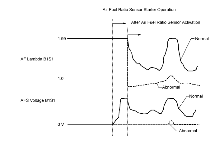
Drive the vehicle until the value of Exhaust Temperature B1S3 becomes 300°C (572°F) or more to activate the air fuel ratio sensors.
Tech Tips
Activation of the air fuel ratio sensor can be checked by confirming whether the value of AF Lambda B1S1 has changed from 1.99.
-
Check that there is no problem on driving performance such as hesitation, knocking, rough idling, insufficient power and acceleration stumbling, or white smoke in emissions.
Tech Tips
-
The air fuel ratio sensor does not operate until the vehicle has been driven for a period of time with an exhaust gas temperature of 200°C (392°F) or more.
-
Perform diagnosis when the air fuel ratio sensor is operating and active.
-
Normal condition in the illustration is only an example. "AF Lambda B1S1" changes depending on driving conditions. If it changes at the range more than 1.0, it is normal.
Result Result Proceed to There is no problem with driving performance such as hesitation, knocking, rough idling, insufficient power or acceleration stumbling, but excessive white smoke is present in the exhaust gas A Except above B Tech Tips
If white smoke is present in the exhaust gas without any driving performance problems such as hesitation, knocking, rough idling, insufficient power or acceleration stumbling, fuel injected due to a malfunction in the exhaust fuel addition injector assembly is the suspected cause of the white smoke.
-
B
CHECK FUEL INJECTION SYSTEM Click here
A
-
-
REPLACE EXHAUST FUEL ADDITION INJECTOR ASSEMBLY
-
Replace the exhaust fuel addition injector assembly Click here.
NEXT
-
-
CLEAN FUEL FILTER CASE AND REPLACE FUEL FILTER
-
Clean the fuel filter case and replace the fuel filter.
Tech Tips
Be sure to clean the inside of the fuel filter case as the fuel injectors may not operate properly if the fuel filter is installed with foreign matter remaining inside the fuel filter case.
NEXT
-
-
PERFORM PM FORCED REGENERATION
-
Connect the intelligent tester to the DLC3.
-
Turn the ignition switch to ON and turn the tester on.
-
Clear the DTCs Click here.
-
Perform PM forced regeneration Click here.
Result PM forced regeneration completes normally.
NG
CHECK FUEL INJECTION SYSTEM Click here
OK 
END
-
-
CHECK FUEL INJECTION SYSTEM
-
Check the fuel injection system Click here.
NEXT
-
-
CHECK INTAKE / EXHAUST SYSTEM
-
Check the intake/exhaust system Click here.
NEXT
-
-
CHECK AFTER TREATMENT CONTROL SYSTEM
-
Check the after treatment control system Click here.
NEXT
CONFIRM WHETHER MALFUNCTION HAS BEEN SUCCESSFULLY REPAIRED Click here
-
-
GO TO DTC CHART
-
Perform inspection and repair of relevant DTCs Click here.
NEXT
CONFIRM WHETHER MALFUNCTION HAS BEEN SUCCESSFULLY REPAIRED Click here
-
-
CHECK AND REPLACE TURBOCHARGER SUB-ASSEMBLY
-
Check for oil leaks and white smoke from the turbocharger sub-assembly and perform any necessary repairs Click here.
Tech Tips
Other than a malfunction of the turbocharger subassembly, exhaust valve stem oil leaks are suspected.
NEXT
-
-
CONFIRM WHETHER MALFUNCTION HAS BEEN SUCCESSFULLY REPAIRED
-
Connect the intelligent tester to the DLC3.
-
Turn the ignition switch to ON and turn the tester on.
-
Clear the DTCs Click here.
-
Perform PM forced regeneration Click here.
NEXT
END
-