SUCTION CONTROL VALVE INSTALLATION

-
INSTALL SUCTION CONTROL VALVE ASSEMBLY
Note
-
Before replacing the suction control valve, be sure to clean the surrounding area.
-
When replacing the suction control valve, make sure that your hands are clean and do not use gloves, etc.
-
Be careful as the installation procedure differs depending on the type of suction control valve.
Tech Tips
There are different types of suction control valve assemblies as shown in the illustration. Therefore, be sure to refer to the replacement table below when replacing the suction control valve assembly.
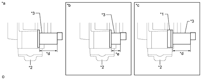
Text in Illustration *1 Attachment *2 Injection Pump *3 Suction Control Valve - - *a SV1 Type *b SV2 Type *c SV1 Type with Attachment *d 45 mm (1.77 in.) *e 23 mm (0.906 in.) - - Suction Control Valve Assembly Replacement Table Suction Control Valve Assembly Currently Installed on Vehicle Replacement Part to Use SV1 Type SV1 Type SV2 Type SV1 Type with Attachment SV1 Type with Attachment SV1 Type with Attachment
-
Apply engine oil to a new O-ring.
Note
-
Be sure to use clean engine oil.
-
As the type of O-ring differs depending on the type of suction control valve, be sure to check the following table before installation.
Type of Suction Control Valve Assembly O-ring Inner Diameter SV1 Type 22.8 mm (0.898 in.) SV1 Type with Attachment 19.8 mm (0.780 in.) -
-
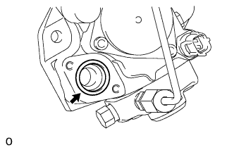
Install the O-ring to the O-ring groove of the injection pump.
Note
Make sure that the O-ring and O-ring groove are free of foreign matter and are not damaged.
-
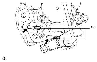
Text in Illustration *1 Guide Pin Install guide pins used for the insertion of the suction control valve to the bolt holes.
Tech Tips
-
When installing the guide pins, it is sufficient to fix them lightly in place by hand.
-
The guide pins are used to make sure that the suction control valve remains perpendicular to the injection pump when it is inserted.
-
-
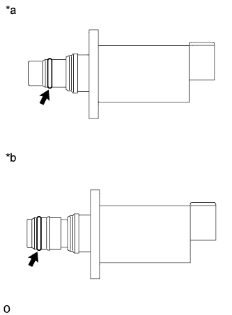
Text in Illustration *a SV1 Type *b SV1 Type with Attachment Apply engine oil to the O-ring at the end of the suction control valve.
Note
Be sure to use clean engine oil.
-
SV1 Type:
-
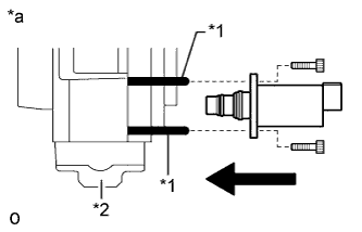
Text in Illustration *1 Guide Pin *2 Injection Pump *a SV1 Type While making sure that the suction control valve and injection pump remain perpendicular to each other, slide the suction control valve along the guide pins and insert it into the injection pump as shown in the illustration.
Note
-
Make sure that the contact surfaces of the injection pump and suction control valve are free of foreign matter and are not damaged.
-
Do not insert the suction control valve at an angle.
-
Make sure that the O-ring does not get pinched between the parts. If it does, replace it with a new one.
-
Insert the suction control valve until it contacts the injection pump.
-
-
While holding the suction control valve in place, remove the guide pins, temporarily install 2 new bolts and uniformly tighten them by hand.
Note
Do not use tools. Tighten the bolts by hand until the surfaces of the suction control valve and injection pump contact each other.
-
Using a 5 mm hexagon wrench, uniformly tighten the 2 bolts.
- Torque:
- 9.0 N*m { 92 kgf*cm, 80 in.*lbf }
-
Connect the connector to the suction control valve.
Note
Make sure that there is not excessive slack or tension in the wire harness of the suction control valve.
-
-
SV1 Type with Attachment:
-
Apply engine oil to a new O-ring.
Note
Be sure to use clean engine oil.
Tech Tips
The inner diameter of the O-ring is 22.8 mm (0.898 in.).
-
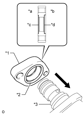
Text in Illustration *1 Attachment *2 New O-ring *3 Suction Control Valve (SV1 Type with Attachment) *a Injection Pump Side *b Suction Control Valve Side *c O-ring Groove (Shallow) *d O-ring Groove (Deep) Install the O-ring to the deep O-ring groove on the attachment, and then temporarily install the attachment to the suction control valve.
Note
-
When installing the attachment, make sure that the deep O-ring groove is facing the suction control valve.
-
Make sure that the O-ring and O-ring groove are free of foreign matter and are not damaged.
-
Make sure that the contact surfaces of the suction control valve and attachment are free of foreign matter and are not damaged.
-
-
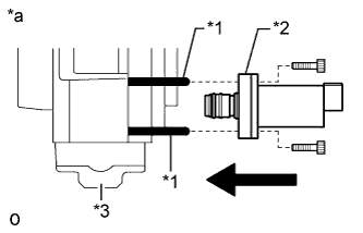
Text in Illustration *1 Guide Pin *2 Attachment *3 Injection Pump *a SV1 Type with Attachment While making sure that the suction control valve and injection pump remain perpendicular to each other, slide the suction control valve and attachment together as a set along the guide pins and insert the suction control valve into the injection pump as shown in the illustration.
Note
-
Make sure that the contact surfaces of the injection pump and attachment are free of foreign matter and are not damaged.
-
Do not insert the suction control valve at an angle.
-
Make sure that the O-ring does not get pinched between the parts. If it does, replace it with a new one.
-
Insert the suction control valve until the attachment contacts the injection pump.
-
-
While holding the suction control valve in place, remove the guide pins, temporarily install 2 new bolts and uniformly tighten them by hand.
Note
Do not use tools. Tighten the bolts by hand until the surfaces of the suction control valve and attachment, and the surfaces of the attachment and injection pump contact each other.
-
Using a 5 mm hexagon wrench, uniformly tighten the 2 bolts.
- Torque:
- 9.0 N*m { 92 kgf*cm, 80 in.*lbf }
-
Connect the connector to the suction control valve.
Note
Make sure that there is not excessive slack or tension in the wire harness of the suction control valve.
-
-
-
INSTALL INJECTION OR SUPPLY PUMP ASSEMBLY
-
BLEED AIR FROM FUEL SYSTEM
-
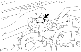
Using the hand pump mounted on the fuel filter cap, bleed the air from the fuel system. Continue pumping until the pump resistance increases.
Note
-
Hand pump pumping speed: Max. 2 strokes/ sec.
-
The hand pump must be pushed with a full stroke during pumping.
-
When the fuel pressure at the supply pump inlet port reaches a saturated pressure, the hand pump resistance increases.
-
If pumping is interrupted during the air bleeding process, fuel in the fuel line may return to the fuel tank. Continue pumping until the hand pump resistance increases.
-
If the hand pump resistance does not increase despite consecutively pumping 200 times or more, there may be a fuel leak between the fuel tank and fuel filter, the hand pump may be malfunctioning, or the vehicle may have run out of fuel.
-
If air bleeding using the hand pump is incomplete, the common rail pressure does not rise to the pressure range necessary for normal use, and the engine cannot be started.
-
-
Start the engine.
Note
-
Even if air bleeding using the hand pump has been completed, the starter may need to be cranked for 10 seconds or more to start the engine.
-
Do not crank the engine continuously for more than 20 seconds. The battery may be discharged.
-
Use a fully-charged battery.
-
When the engine can be started, proceed to the next step.
-
If the engine cannot be started, bleed the air again using the hand pump until the hand pump resistance increases (refer to the procedures above). Then start the engine.
-
-
Turn the ignition switch off.
-
Connect the intelligent tester to the DLC3.
-
Turn the ignition switch to ON and turn the intelligent tester on.
-
Clear DTCs Click here.
-
Start the engine.*1
-
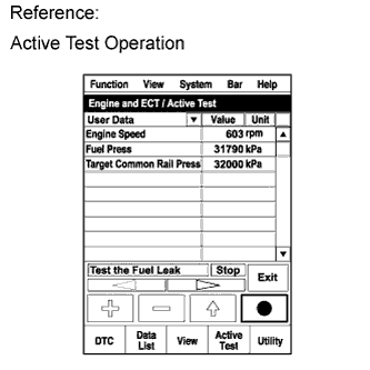
Enter the following menus: Powertrain / Engine and ECT / Active Test / Test the Fuel Leak.*2
-
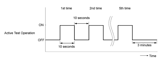
Perform the following test 5 times with on/off intervals of 10 seconds: Active Test / Test the Fuel Leak.*3
-
Allow the engine to idle for 3 minutes or more after performing the Active Test for the fifth time.
Tech Tips
When the Active Test "Test the Fuel Leak" is used to change the pump control mode, the actual fuel pressure inside the common rail drops below the target fuel pressure when the Active Test is off, but this is normal and does not indicate a pump malfunction.
-
Enter the following menus: Powertrain / Engine and ECT / DTC.
-
Read Current DTCs.
-
When no DTCs are output, the air bleeding is completed.
-
If any DTCs are output, proceed to the next step.
-
-
Clear the DTCs Click here.
-
Repeat steps *1 to *3.
-
Enter the following menus: Powertrain / Engine and ECT / DTC.
-
Read Current DTCs.
OK No DTCs are output.
-
-
SUPPLY PUMP INITIALIZATION PROCEDURE
-
INSPECT FOR FUEL LEAK
-
Perform the Active Test.
-
Connect the intelligent tester to the DLC3.
-
Turn the ignition switch ON.
-
Turn the intelligent tester ON.
-
Select the following menu items: Powertrain / ECD / Active Test.
-
Perform the Active Test.
Intelligent Tester Display Test Details Control Range Diagnostic Notes Test the Fuel Leak Pressurizes common rail internal fuel pressure, and checks for fuel leaks Stop/Start
-
Fuel pressure inside common rail pressurized to specified value and engine speed increased to 2,000 rpm when ON is selected
-
Above conditions preserved while test is ON
-
-
-