FUEL TEMPERATURE SENSOR REMOVAL

-
DISCONNECT CABLE FROM NEGATIVE BATTERY TERMINAL
-
DRAIN ENGINE COOLANT
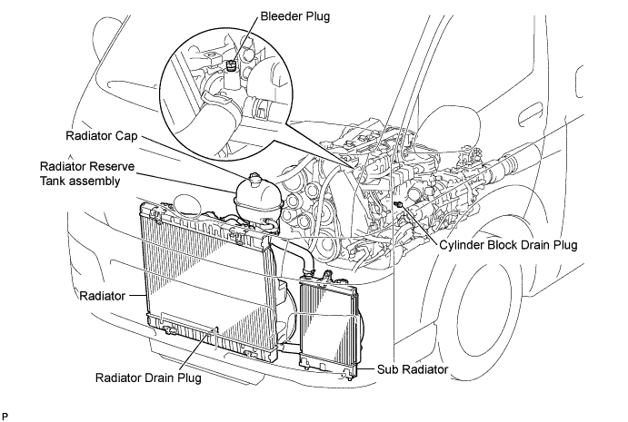
CAUTION:
To avoid the danger of being burned, do not remove the radiator reserve tank cap while the engine and radiator are still hot. Thermal expansion will cause hot engine coolant and steam to blow out from the radiator.
-
Loosen the radiator drain plug (on the radiator).
-
Remove the radiator cap.
-
Loosen the engine drain plug (on the engine oil cooler cover), and drain the coolant.
-
Tighten the engine drain plug (on the radiator).
-
Tighten the engine drain plug (on the engine oil cooler cover).
- Torque:
- 8.0 N*m { 82 kgf*cm, 71 in.*lbf }
-
-
REMOVE FRONT SEAT ASSEMBLY RH
-

Move the front seat assembly fully forward.
-
Remove the 2 bolts on the rear side of the seat.
-
Move the front seat assembly to the rearmost position.
-
Remove the 2 bolts on the front side of the seat.
-
Move the front seat assembly to the center of the seat slide rail. Set the seatback in the upright position.
-
Disconnect the front seat inner belt assembly connector.
-
Remove the front seat assembly.
-
-
REMOVE FRONT DOOR SCUFF PLATE RH
-
REMOVE ENGINE SERVICE HOLE SUB COVER SUB-ASSEMBLY
-
Roll up the carpet, and remove the 5 bolts and engine service hole sub cover sub-assembly.
-
-
REMOVE FAN & GENERATOR V BELT
-
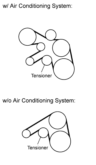
Remove the drive belt by rotating the tensioner pulley clockwise to loosen its tension with the pulley set bolt of the tensioner.
-
-
REMOVE NO. 1 TIMING BELT COVER
-
Remove the wire harness clamp.
-
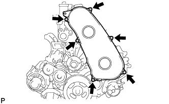
Remove the 6 bolts and timing belt cover.
-
-
REMOVE TIMING BELT
-
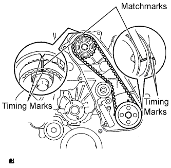
Set the No. 1 cylinder to TDC/ compression.
-
Turn the crankshaft clockwise and align the timing marks as shown in the illustration.
Tech Tips
If reusing the timing belt, draw a direction arrow on the belt (in the direction of engine revolution) and place matchmarks on the pulleys and belt as shown in the illustration.
-
-
Alternately loosen the 2 bolts, and remove the timing belt tensioner.
-

Remove the timing belt.
Tech Tips
-
When turning the camshaft with the timing belt removed, first turn the crankshaft 90° counterclockwise to lower the piston.
-
When installing the timing belt, first return the camshaft to the timing marks and then turn the crankshaft clockwise until it aligns with the timing marks.
-
-
-
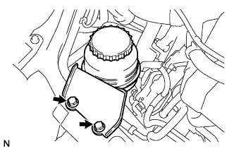
SEPARATE VANE PUMP OIL RESERVOIR ASSEMBLY
-
Remove the 2 bolts, and separate the vane pump oil reservoir assembly.
-
-
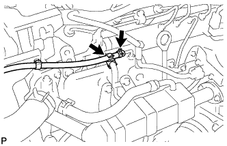
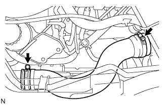
DISCONNECT OIL RETURN HOSE
-
Loosen the 2 clips.
-
Disconnect the oil return hose.
-
-
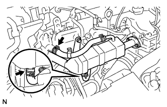
REMOVE EGR COOLER ASSEMBLY
-
Loosen the clip and disconnect the No. 4 water by-pass hose.
-
Loosen the clip and disconnect the No. 2 water by-pass hose.
-
Remove the 3 bolts and 2 nuts and remove the EGR cooler assembly.
-
-
REMOVE NO. 4 AIR HOSE
-
Loosen the 2 clamps.
-
Remove the No. 4 air hose .
-
-
REMOVE DIESEL THROTTLE BODY ASSEMBLY
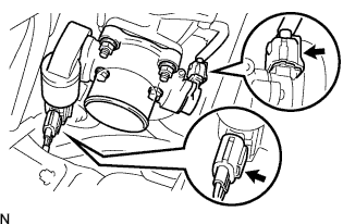
-
Disconnect the 2 throttle body connectors.
-
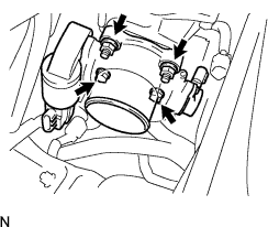
Remove the 2 bolts, 2 nuts and diesel throttle body assembly.
-
Remove the gasket from the intake air connector.
-
-
REMOVE OIL LEVEL GAUGE GUIDE
-
Remove the oil level gauge.
-
Remove the bolt and remove the oil level gauge guide.
-
-
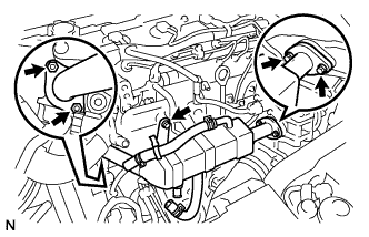
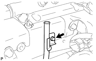
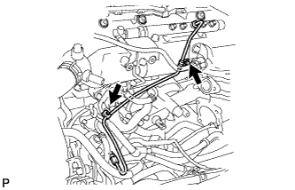
REMOVE FUEL INLET PIPE SUB-ASSEMBLY
-
Remove the 2 clamp bolts.
-
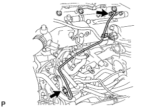
Using SST, loosen the 2 union nuts and remove the fuel inlet pipe sub-assembly.
- SST
- 09023-12701
-
-
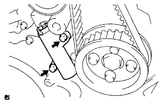
REMOVE VANE PUMP ASSEMBLY
-
REMOVE INJECTION OR SUPPLY PUMP ASSEMBLY
-
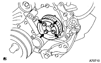
Remove the 4 bolts.
-
Remove the No. 2 camshaft timing pulley flange and pump drive shaft pulley.
-
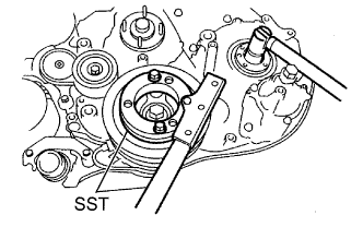
Using SST, remove the supply pump gear set nut and O-ring while holding the crankshaft pulley.
- SST
- 09213-58013
- 09330-00021
-
Disconnect the 2 fuel hoses.
-
Disconnect the 2 connectors and wire harness.
-
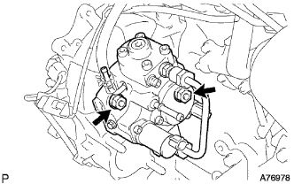
Loosen the 2 nuts as shown in the illustration.
-
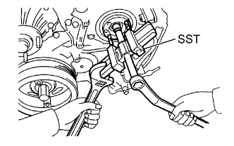
Using SST, disengage the fuel supply pump from the supply pump gear.
- SST
- 09950-50013 ( 09951-05010, 09952-05010, 09953-05020, 09954-05021 )
-
Remove the 2 nuts and fuel supply pump from the engine.
-
Remove the O-ring from the fuel supply pump.
-
Remove the pulley key from the fuel supply pump.
-
-
REMOVE FUEL TEMPERATURE SENSOR
-
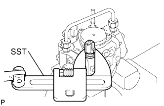
Mount the fuel supply pump in a soft jaw vise.
-
Using a SST, remove the fuel temperature sensor.
- SST
- 09922-10010
-
Remove the O-ring from the fuel temperature sensor.
-