REPAIR INSTRUCTION INITIALIZATION
Note
When disconnecting the cable from negative (-) battery terminal, initialize the following system(s) after the terminal is reconnected.
-
The initialization procedures are show below the table.
| System Name |
|---|
| Power Window Control System |
| Power Slide Door System |
-
REGISTRATION RELATED TO ECD SYSTEM (for 1KD-FTV, w/DPF)
-
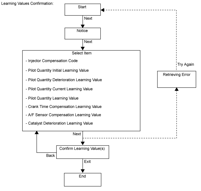
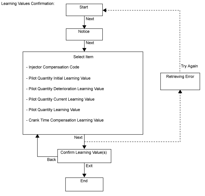
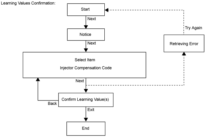
LEARNING VALUES CONFIRMATION
This procedure uses the GTS to display the learned values (injector compensation code, pilot quantity initial learning value, pilot quantity deterioration learning value, pilot quantity current learning value, pilot quantity learning value, crank time compensation learning value, A/F sensor learning value and catalyst deterioration learning value) stored in the ECM.
Tech Tips
-
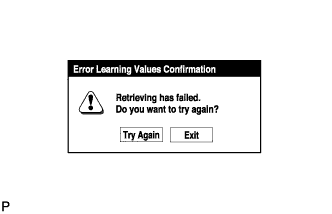
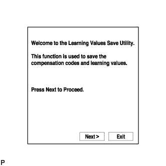
A malfunction may occur when reading the values if there is a problem with the ECM, a wire harness or the connection to the DLC3. If the wire harnesses and the connection to the DLC3 are inspected and found to be normal, the ECM may be malfunctioning.
-
Connect the GTS to the DLC3.
-
Turn the ignition switch to ON and turn the GTS on.
Note
Do not start the engine.
-
Enter the following menus: Powertrain / Engine and ECT / Utility / Learning values confirmation.
-
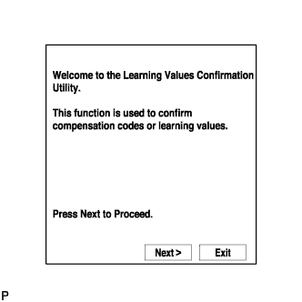
Press "Next".
-
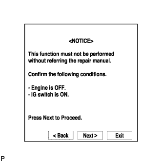
Press "Next" again to proceed.
-
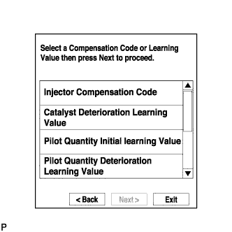
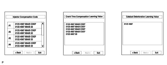
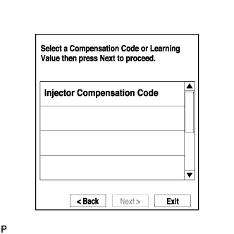
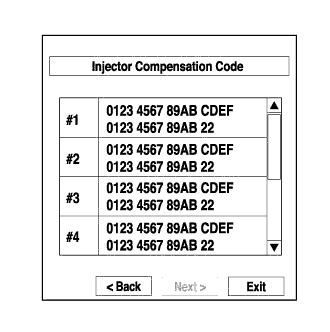
Select the value to confirm and press "Next".
-
When the next screen is displayed, confirm the contents and press "Exit".
-
-
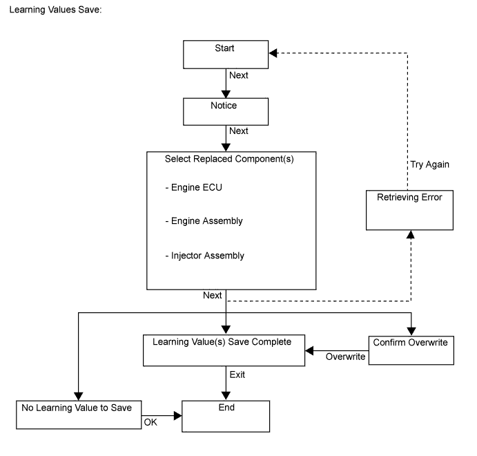
LEARNING VALUES SAVE
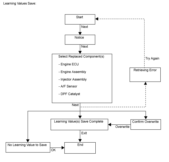
This procedure uses the GTS to save the learned values (injector compensation code, pilot quantity learning value, crank time compensation learning value, catalyst deterioration learning value and A/F sensor learning value) stored in the ECM in the GTS depending on the components being replaced.
Tech Tips
-
When replacing the engine assembly, injector assembly, catalyst converter or the A/F sensor together with the ECM, this function automatically determines the data which can be transferred (old data) and saves the data in the GTS.
-
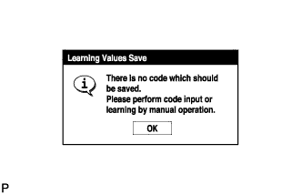
When there is no data to read from the ECM, manually perform the procedure to register each compensation code and learning value in the ECM.
-
A malfunction may occur when reading the values if there is a problem with the ECM, a wire harness or the connection to the DLC3. If the wire harnesses and the connection to the DLC3 are inspected and found to be normal, the ECM may be malfunctioning.
-
Connect the GTS to the DLC3.
-
Turn the ignition switch to ON and turn the GTS on.
Note
Do not start the engine.
-
Enter the following menus: Powertrain / Engine and ECT / Utility / Learning values save.
-
Press "Next".
-
Press "Next" again to proceed.
-
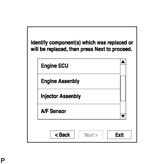
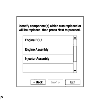
Select any components being replaced and press "Next". If no applicable components are displayed, press "Next" without selecting anything.
-
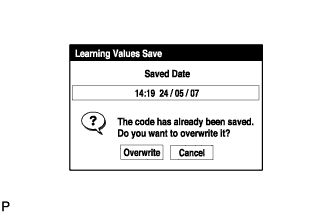
If the overwrite confirmation screen is displayed, press "Overwrite".
-
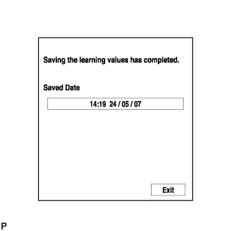
When the operation is finished, confirm the date and time of the save operation, and press "Exit".
-
-
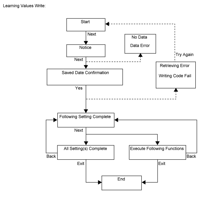
LEARNING VALUES WRITE
This procedure uses the GTS to write all of the learned values (injector compensation code, pilot quantity learning value, crank time compensation learning value, catalyst deterioration learning value and A/F sensor learning value) stored in the GTS to the ECM.
Tech Tips
-
A malfunction may occur when writing the values if there is a problem with the ECM, a wire harness or the connection to the DLC3. If the wire harnesses and the connection to the DLC3 are inspected and found to be normal, the ECM may be malfunctioning.
-
Connect the GTS to the DLC3.
-
Turn the ignition switch to ON and turn the GTS on.
Note
Do not start the engine.
-
Enter the following menus: Powertrain / Engine and ECT / Utility / Learning values write.
-
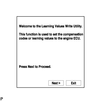
Press "Next".
-
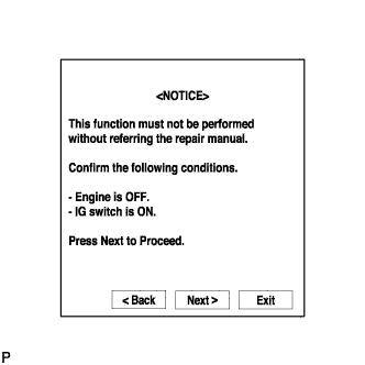
Press "Next" again to proceed.
-
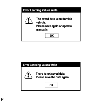
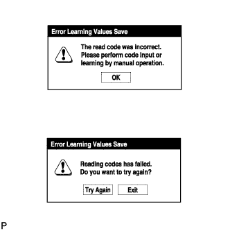
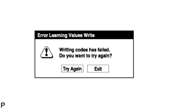
If the "Error Learning Values Write" screen indicating a problem with the saved value(s) or that there are no saved values is displayed, perform "Learning Values Save" again.
-
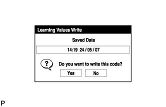
Confirm the date and time of the save operation, and then press "Yes".
-
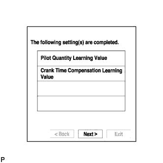
Confirm the contents, and then press "Next".
-
If any instructions are displayed on the GTS, manually perform the procedure to register each applicable compensation code or learning value in the ECM.
-
Clear the DTCs.
-
-
INPUT INJECTOR COMPENSATION CODE(S) INTO ECM
Note
-
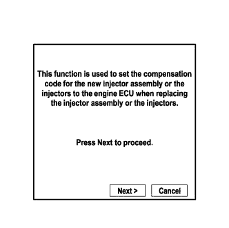
When a fuel injector is replaced, the new fuel injector compensation code must be input into the ECM. When the ECM is replaced, all of the existing fuel injector compensation codes must be input into the new ECM.
-
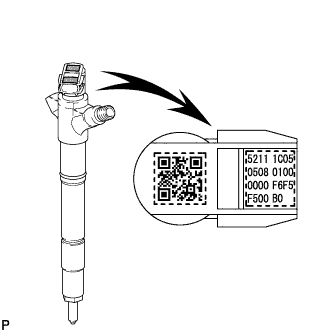
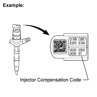
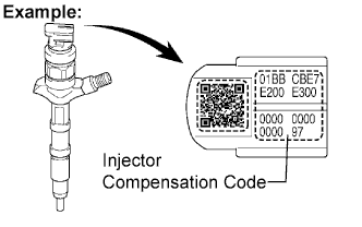
Fuel injector compensation codes are unique, 30-digit, alphanumeric values printed on the head portion of each fuel injector. If an incorrect fuel injector compensation code is input into the ECM, the engine assembly may rattle or engine idling may become rough. In addition, engine failure may occur and the life of the engine may be shortened.
-
When a fuel injector compensation code is input into the ECM, the pilot quantity learning values stored in the ECM are initialized. Also, DTC P062F is stored when the pilot quantity learning values are initialized.
Text in Illustration *a Example *b Injector Compensation Code
-
After replacing fuel injector(s) with new one(s), input compensation code(s) of the fuel injector(s) into the ECM as follows:
Tech Tips
-
Each fuel injector has different fuel injection characteristics. In order to optimize the fuel injections, the ECM uses the compensation codes to balance the different fuel injections between each fuel injector.
-
When only one or more fuel injectors are replaced, input the fuel injector compensation code(s), perform pilot quantity learning, and then clear the DTCs.
-
When the ignition switch is turned to ON after replacing the ECM, DTC P062F is stored. This indicates that the fuel injector compensation code(s) need to be registered. Manually clear the DTC upon completion of pilot quantity learning.
-
Input the compensation code(s), which is/are imprinted on the head portion(s) of the new fuel injector(s), into the GTS.
-
Input the new compensation code(s) into the ECM using the GTS.
-
Turn the GTS off and turn the ignition switch off.
-
Wait for at least 30 seconds.
-
Turn the ignition switch to ON and turn the GTS on.
-
Perform pilot quantity learning.
-
Clear DTC P062F stored in the ECM using the GTS.
Note
If the DTCs are cleared without performing pilot quantity learning, DTC P062F is stored immediately after clearing DTCs.
-
-
Register compensation codes.
-
Connect the GTS to the DLC3.
-
Turn the ignition switch to ON.
Note
Do not start the engine.
-
Turn the GTS on.
-
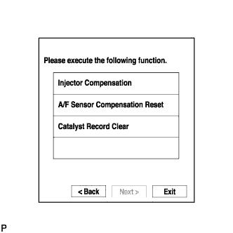
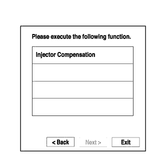
Enter the following menus: Powertrain / Engine and ECT / Utility / Injector Compensation.
-
Press Next.
-
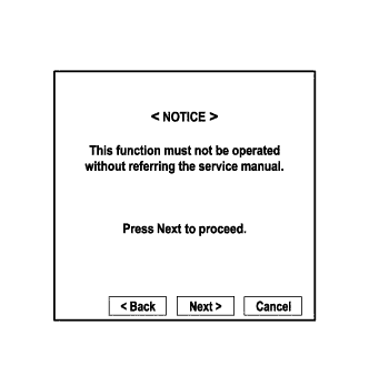
Press Next again to proceed.
-

Select "Set Compensation Code".
-
Press Next.
-
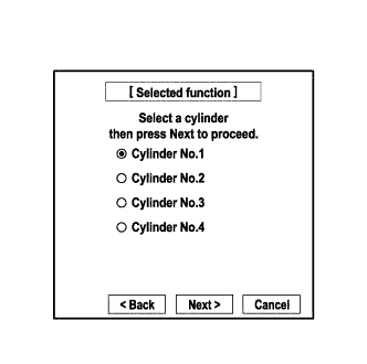
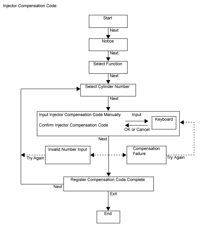
Select the number of the cylinder corresponding to the fuel injector compensation code that you want to register.
-
Press Next.
-
Register compensation code.
-
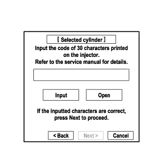
Press Input.
-
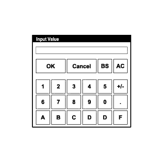
Manually input the cylinder compensation code using the keyboard on the GTS screen. The code is a 30-digit, alphanumeric value printed on the injector head portion.
Tech Tips
Each fuel injector compensation code is unique. The compensation code for each selected cylinder must be input into the GTS correctly.
-
Confirm that the compensation code for the selected cylinder is correct, and then press OK.
-
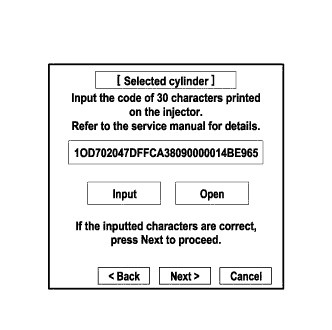
Check that the compensation code displayed on the screen is correct by comparing it with the 30-digit alphanumeric value on the head portion of the fuel injector.
Note
If an incorrect fuel injector compensation code is input into the ECM, the engine may rattle or engine idling may become rough. In addition, engine failure may occur and the life of the engine may be shortened.
Tech Tips
-
If a wrong compensation code is input or read, return to the Input Value screen by pressing Input.
-
The saving process may fail due to a problem with the wire harness or a bad connection with the DLC3. Check the wire harness and DLC3 connection. If no problem is found with either, the ECM may be malfunctioning. Check the ECM and repeat this operation.
-
-
Press Next to register the compensation code in the ECM.
Tech Tips
-
If the registration process fails, the compensation code may be incorrect. Check the compensation code again.
-
If the input compensation code fails to register even though it is input correctly, there may be a problem with the wire harness or a bad connection with the DLC3. Check the wire harness and DLC3 connection. If no problem is found with either, the ECM may be malfunctioning. Check the ECM and restart this operation.
-
-
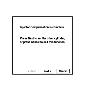
If you want to continue with other compensation code registrations, press Next. To finish the registration, press Exit.
-
Turn the GTS off and turn the ignition switch off.
-
Wait for at least 30 seconds.
-
Turn the ignition switch to ON, and then turn the GTS on.
-
Perform pilot quantity learning.
-
Clear DTC P062F stored in the ECM using the GTS.
Note
If the DTCs are cleared without performing pilot quantity learning, DTC P062F is stored immediately after clearing DTCs.
-
-
-
PILOT QUANTITY LEARNING
-
"Pilot Quantity Learning" is performed when injector assemblies have been replaced and injector compensation codes have been registered. "Pilot Quantity Learning (Detail)" is performed when there are engine problems but no DTCs are output and the technician wishes to clear the learned values and have the vehicle relearn the values.
-
This procedure uses the GTS to perform "Pilot Quantity Learning".
-
When replacing the injector assembly, engine or ECM, perform this procedure after performing injector compensation (manual ID code registration).
Note
After completing this procedure, clear the DTCs using the GTS.
Tech Tips
-
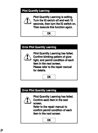
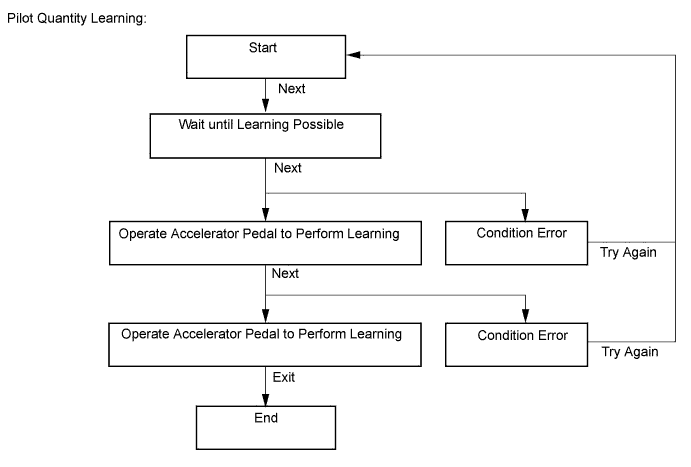
If "Exit" is pushed during the step where the accelerator pedal is operated and "Pilot Quantity Learning" is canceled, turn the ignition switch off, wait 10 seconds, check the vehicle condition, and then perform learning again.
-
If an error occurs during learning, check the vehicle condition after turning the ignition switch off, and then perform learning again.
-
If learning is canceled and DTCs are output due to excessive racing of the engine (depressing the accelerator pedal for 2 seconds or more), turn the ignition switch off, and then perform learning again.
-
A communication malfunction may occur if there is a problem with the ECM, a wire harness or the connection to the DLC3. If the wire harnesses and the connection to the DLC3 are inspected and found to be normal, the ECM may be malfunctioning.
-
Connect the GTS to the DLC3.
-
Start the engine.
-
Turn the GTS on.
-
Enter the following menus: Powertrain / Engine and ECT / Utility / Pilot quantity learning.
-
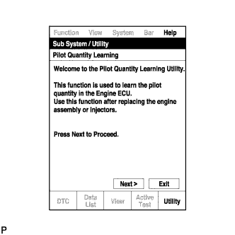
Press "Next".
-
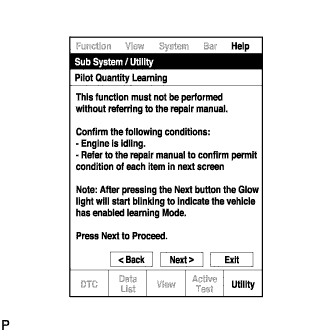
Press "Next" again to proceed.
-
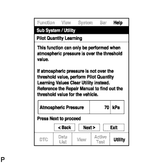
Confirm that the atmospheric pressure screen is displayed.
-
Confirm the displayed atmospheric pressure.
Standard Atmosphere Pressure is 85 kPa or more Note
-
If the atmospheric pressure is below the standard range, "Pilot Quantity Learning" cannot be performed. In this case, press "Exit" and clear the learned values using "Pilot Quantity Learning Value Clear".
-
If the atmospheric pressure is below the standard range, even if "Pilot Quantity Learning" is performed, learning will not be completed.
-
-
If the atmospheric pressure is within the standard range, proceed to the next screen.
-
-
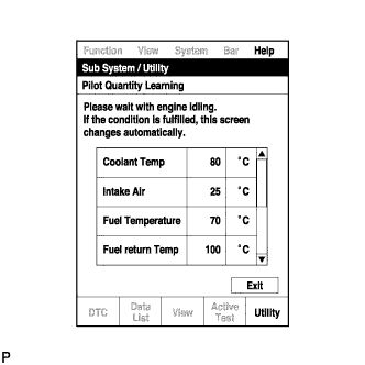
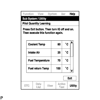
Confirm the condition of the engine and wait until learning can be performed.
Essential Conditions for Learning Tester Display Standard Coolant Temp 70 to 100°C Intake Air 10 to 120°C Fuel Temperature 25 to 96°C Fuel Return Temp 55 to 110°C Battery Voltage 10 V or higher Pilot Quantity State (CAT) READY Tech Tips
-
If the values deviate from the standard above, "Pilot Quantity Learning" enters a standby state or is canceled.
-
When the display indicates that "Pilot Quantity State (CAT)" is prohibited, perform "Pilot Quantity Learning" after performing the "Activate the DPF Rejuvenate (PM)" Active Test using the GTS.
-
When the essential conditions to perform learning are met, the screen will change automatically.
Note
-
If "Activate the DPF Rejuvenate (PM)" is performed after an injector compensation code is input but before "Pilot Quantity Learning" is performed, DTC P062F is stored and the MIL illuminates due to "Pilot Quantity Learning" being incomplete.
-
Using the GTS, make sure that DTCs other than DTC P062F are not output.
-
If DTCs other than DTC P062F are output, perform troubleshooting for those DTCs, and then perform "Activate the DPF Rejuvenate (PM)".
Tech Tips
DTC P062F is stored when the value registered in the ECM for an input injector compensation code, catalyst deterioration learning value and/or pilot quantity deterioration learning value is the initial value.
-
Tech Tips
DTC P062F is stored when the value registered in the ECM for an input injector compensation code, catalyst deterioration learning value and/or pilot quantity deterioration learning value is the initial value.
-
-
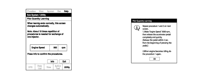
Follow the prompts on the screen and repeat the following procedure until the screen changes: Starting with the engine idling, race the engine until the engine speed is 3000 rpm or more for no more than 2 seconds, and then let the engine return to idling.
Tech Tips
-
After confirming that the engine speed has reached 3000 rpm, completely release the accelerator pedal in order for the throttle opening amount to become 0%.
-
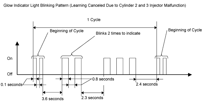
It is possible to confirm the status of the learning operation during "Pilot Quantity Learning" by observing the blinking pattern of the glow indicator light.
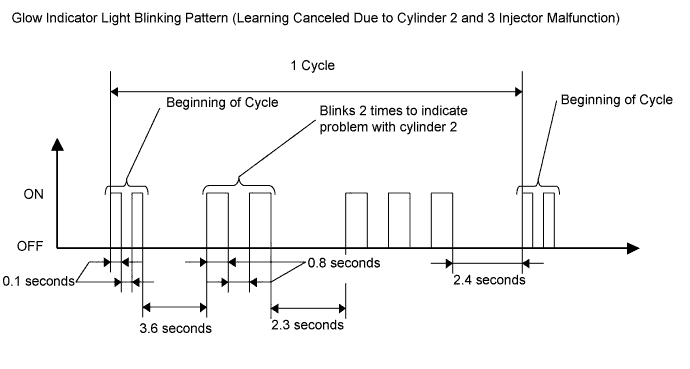
Glow Indicator Light Blinking Pattern Learning Status Glow Indicator Light Condition Conditions essential to start learning have not been met Blinking at 0.5 second intervals Conditions essential to start learning have been met Blinking at 1 second intervals During racing (learning is being performed) Blinking at 1 second intervals Learning is finished Off Learning has been canceled Blinking at 1.5 second intervals Learning has been canceled (malfunctioning cylinder is indicated by blinking pattern) Blinking at 0.8 second intervals (2.3 second intervals between each set of blinks representing the number of a malfunctioning cylinder) 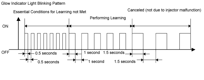
-
-
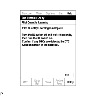
When the screen changes, push "Exit".
-
Turn the GTS off and turn the ignition switch off.
-
Wait for at least 10 seconds.
-
Turn the ignition switch to ON, and then turn the GTS on.
-
Clear the DTCs.
-
Turn the ignition switch off.
Note
Do not disconnect the cable from the negative (-) battery terminal for 30 seconds after turning the ignition switch off.
Tech Tips
-
The main relay turns off after the learned value is stored in the ECM.
-
The main relay turns off within approximately 5 to 10 seconds of turning the ignition switch off.
-
-
-
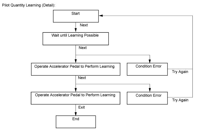
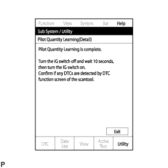
PILOT QUANTITY LEARNING (DETAIL)
-
"Pilot Quantity Learning" is performed when injector assemblies have been replaced and injector compensation codes have been registered. "Pilot Quantity Learning (Detail)" is performed when there are engine problems but no DTCs are output and the technician wishes to clear the learned values and have the vehicle relearn the values.
It takes time to clear the learned values and perform learning for all cylinders.
-
This procedure uses the GTS to perform "Pilot Quantity Learning (Detail)".
-
When replacing the injector assembly, engine or ECM, perform this procedure after performing injector compensation (manual ID code registration).
Note
After completing this procedure, clear the DTCs using the GTS.
Tech Tips
-
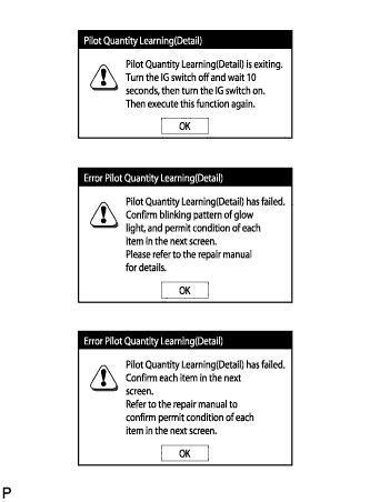
If "Exit" is pushed during the step where the accelerator pedal is operated and "Pilot Quantity Learning (Detail)" is canceled, turn the ignition switch off, wait 10 seconds, check the vehicle condition, and then perform learning again.
-
If an error occurs during learning, check the vehicle condition after turning the ignition switch off, and then perform learning again.
-
If learning is canceled and DTCs are output due to excessive racing of the engine (depressing the accelerator pedal for 2 seconds or more), turn the ignition switch off, and then perform learning again.
-
A communication malfunction may occur if there is a problem with the ECM, a wire harness or the connection to the DLC3. If the wire harnesses and the connection to the DLC3 are inspected and found to be normal, the ECM may be malfunctioning.
-
Connect the GTS to the DLC3.
-
Start the engine.
-
Turn the GTS on.
-
Enter the following menus: Powertrain / Engine and ECT / Utility / Pilot quantity learning (Detail).
-
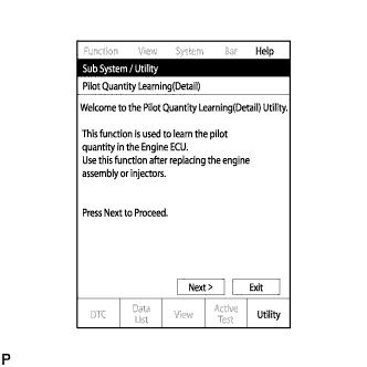
Press "Next".
-
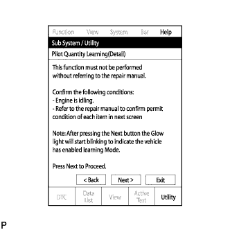
Press "Next" again to proceed.
-
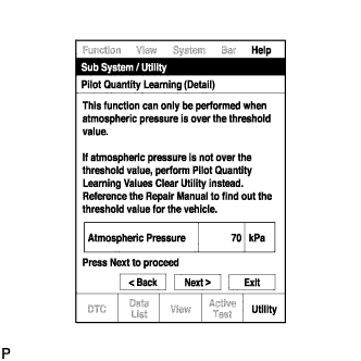
Confirm that the atmospheric pressure screen is displayed.
-
Confirm the displayed atmospheric pressure.
Standard Atmosphere Pressure is 85 kPa or more Note
-
If the atmospheric pressure is below the standard range, "Pilot Quantity Learning" cannot be performed. In this case, press "Exit" and clear the learned values using "Pilot Quantity Learning Value Clear".
-
If the atmospheric pressure is below the standard range, even if "Pilot Quantity Learning" is performed, learning will not be completed.
-
-
If the atmospheric pressure is within the standard range, proceed to the next screen.
-
-
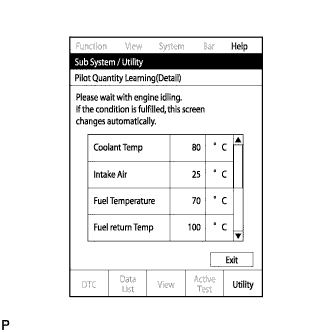
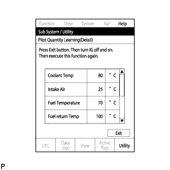
Confirm the condition of the engine and wait until learning can be performed.
Essential Conditions for Learning Tester Display Standard Coolant Temp 70 to 100°C Intake Air 10 to 120°C Fuel Temperature 25 to 96°C Battery Voltage 10 V or higher Pilot Quantity State (CAT) READY Tech Tips
-
If the values deviate from the standard above, "Pilot Quantity Learning (Detail)" enters a standby state or is canceled.
-
When the display indicates that "Pilot Quantity State (CAT)" is prohibited, perform "Pilot Quantity Learning" after performing the "Activate the DPF Rejuvenate (PM)" Active Test using the GTS.
-
When the essential conditions to perform learning are met, the screen will change automatically.
Note
-
If "Activate the DPF Rejuvenate (PM)" is performed after an injector compensation code is input but before "Pilot Quantity Learning" is performed, DTC P062F is stored and the MIL illuminates due to "Pilot Quantity Learning" being incomplete.
-
Using the GTS, make sure that DTCs other than DTC P062F are not output.
-
If DTCs other than DTC P062F are output, perform troubleshooting for those DTCs, and then perform "Activate the DPF Rejuvenate (PM)".
Tech Tips
DTC P062F is stored when the value registered in the ECM for an input injector compensation code, catalyst deterioration learning value and/or pilot quantity deterioration learning value is the initial value.
-
-
Follow the prompts on the screen and repeat the following procedure until the screen changes: Starting with the engine idling, race the engine until the engine speed is 3000 rpm or more for no more than 2 seconds, and then let the engine return to idling.
Tech Tips
-
After confirming that the engine speed has reached 3000 rpm, completely release the accelerator pedal in order for the throttle opening amount to become 0%.
-
It is possible to confirm the status of the learning operation during "Pilot Quantity Learning (Detail)" by observing the blinking pattern of the glow indicator light.
Glow Indicator Light Blinking Pattern Learning Status Glow Indicator Light Condition Conditions essential to start learning have not been met Blinking at 0.5 second intervals Conditions essential to start learning have been met Blinking at 1 second intervals During racing (learning is being performed) Blinking at 1 second intervals Learning is finished Off Learning has been canceled Blinking at 1.5 second intervals Learning has been canceled (malfunctioning cylinder is indicated by blinking pattern) Blinking at 0.8 second intervals (2.3 second intervals between each set of blinks representing the number of a malfunctioning cylinder)
-
-
When the screen changes, push "Exit".
-
Turn the GTS off and turn the ignition switch off.
-
Wait for at least 10 seconds.
-
Turn the ignition switch to ON, and then turn the GTS on.
-
Clear the DTCs.
-
Turn the ignition switch off.
Note
Do not disconnect the cable from the negative (-) battery terminal for 30 seconds after turning the ignition switch off.
Tech Tips
-
The main relay turns off after the learned value is stored in the ECM.
-
The main relay turns off within approximately 5 to 10 seconds of turning the ignition switch off.
-
-
-
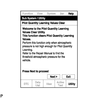
PILOT QUANTITY LEARNING VALUE CLEAR
Tech Tips
-
If the atmospheric pressure is below the threshold value, "Pilot Quantity Learning" will not be completed and DTC P062F is stored. After "Pilot Quantity Learning Value Clear" is performed, DTC P062F will not be stored.
-
Clear the learned values using the following procedure.
-
Connect the GTS to the DLC3.
-
Turn the ignition switch to ON and turn the GTS on.
-
Enter the following menus: Powertrain / Engine and ECT / Utility / Pilot Quantity Learning Value Clear
-
Press "Next".
-
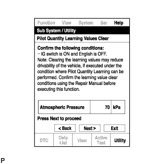
Confirm that the atmospheric pressure screen is displayed.
-
Confirm the displayed atmospheric pressure.
Standard Atmosphere Pressure is below 85 kPa Note
-
If the atmospheric pressure is higher than the standard range for performing "Pilot Quantity Learning Value Clear", do not clear the learned values. Instead, perform "Pilot Quantity Learning".
-
When the atmospheric pressure is higher than the standard range, perform "Pilot Quantity Learning" without initializing the learned values using "Pilot Quantity Learning Value Clear". If the learned values are initialized when the atmospheric pressure is higher than the standard range, the following symptoms may appear. Be sure to correctly follow procedures.
-
Driveability problems
-
Rough idle
-
Emission of white or black smoke, etc.
-
-
Proceed to the next screen.
-
-
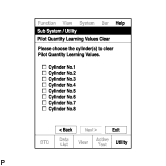
Select the cylinders whose learned value will be cleared.
Note
-
Multiple cylinders can be selected.
-
Only the cylinders for which fuel injector compensation codes have been written must have their learned value cleared.
-
-
After selecting the cylinders whose learned value will be cleared, press "Next" to begin the initialization.
-
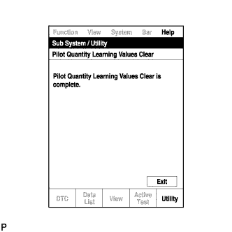
When the screen changes, push "Exit".
-
Turn the GTS off and turn the ignition switch off.
-
Wait for at least 10 seconds.
-
Turn the ignition switch to ON and turn the GTS on.
-
Clear the DTCs.
-
Turn the ignition switch off and leave the vehicle for 30 seconds or more.
-
Turn the ignition switch to ON for 1 second.
-
Enter the following menus: Powertrain / Engine and ECT / Trouble Codes.
-
Read the DTCs.
-
Confirm that no DTCs are output.
-
-
-
INITIALIZATION RELATED TO ECD SYSTEM (for 1KD-FTV, w/DPF)
-
INITIALIZATION PROCEDURE FOR DIESEL THROTTLE BODY ASSEMBLY, ELECTRIC EGR CONTROL VALVE ASSEMBLY AND TURBOCHARGER
Tech Tips
When the diesel throttle body assembly, electric EGR control valve assembly or turbocharger sub-assembly is replaced, perform initialization
-
Turn the ignition switch to ON.
Note
Do not start the engine.
-
Turn the ignition switch off and wait for 30 seconds or more.
-
Turn the ignition switch to ON and wait for 10 seconds or more.
-
-
CATALYST RECORD OF DPF THERMAL DETERIORATION CLEAR FUNCTION
Tech Tips
When the DPF catalyst is replaced, the catalyst record of DPF thermal deterioration stored in the ECM must be cleared.
-
Connect the GTS to the DLC3.
-
Turn the ignition switch to ON.
-
Turn the GTS on.
-
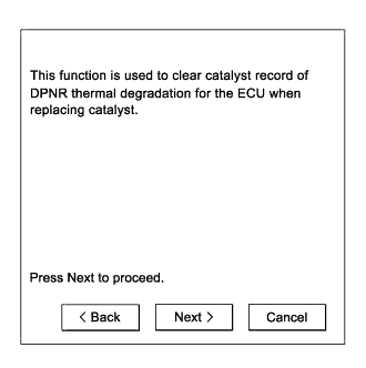
Enter the menu options in this order: Powertrain / Engine and ECT / Utility / Catalyst Record Clear.
-
Press "Next".
-
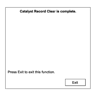
Press "Exit".
-
-
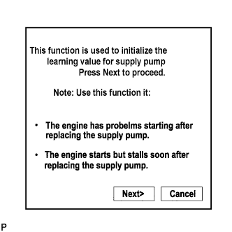
FUEL SUPPLY PUMP INITIALIZATION PROCEDURE
Tech Tips
After replacing the fuel supply pump assembly and/or ECM:
-
If the engine is defective or stalls immediately after startup, the learned values of the ECM must be initialized. The engine can be initialized through the GTS or by connecting DLC3 terminals.
-
If the engine starts normally, initialization is not necessary. Perform the steps labeled procedure "A" and procedure "B" only.
-
Connect the GTS to the DLC3.
-
Turn the ignition switch to ON.
Note
Do not start the engine.
-
Turn the GTS on.
-
Enter the following menus: Powertrain / Engine and ECT / Utility / Supply Pump Initialization.
-
Press "Next".
-
Press "Next".
-
Press "Exit".
-
Start the engine to check if the initialization is complete. If the engine cannot be started, repeat the initialization procedures from the beginning (Procedure "A").
-
Idle the engine for at least 1 minute under the following conditions: (Procedure "B")
-
The engine coolant temperature is 60°C (140°F) or higher.
-
The fuel temperature is 20°C (68°F) or higher.
Note
Do not race the engine immediately after starting the engine. After warming up the engine, racing the engine is acceptable.
Tech Tips
-
The engine coolant temperature can be estimated by touching the outlet hose.
-
The fuel temperature can be estimated by using the ambient temperature as a substitute.
-
If the engine coolant temperature is difficult to estimate, use the GTS and enter the following menus: Powertrain / Engine and ECT / Data List / Coolant Temp.
-
-
Initialization is complete.
-
-
CRANK TIME COMPENSATION RESET FUNCTION
-
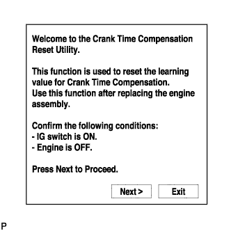
This procedure uses the GTS to perform "Crank Time Compensation Reset".
-
When replacing the timing rotor (engine assembly), perform "Crank Time Compensation Reset".
Tech Tips
-
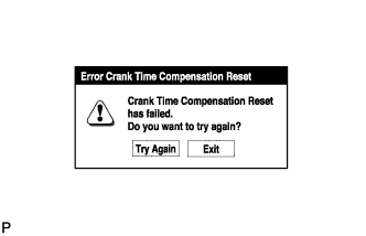
If an error occurs during compensation reset, check the vehicle condition, and then perform compensation reset again.
-
A communication malfunction may occur if there is a problem with the ECM, a wire harness or the connection to the DLC3. If the wire harnesses and the connection to the DLC3 are inspected and found to be normal, the ECM may be malfunctioning.
-
Connect the GTS to the DLC3.
-
Turn the ignition switch to ON.
Note
Do not start the engine.
-
Turn the GTS on.
-
Enter the following menus: Powertrain / Engine and ECT / Utility / Crank Time Compensation Reset.
-
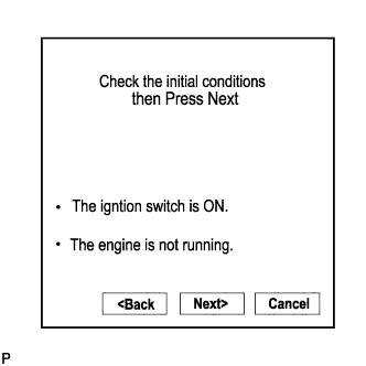
When the first screen is displayed, check the vehicle condition and push "Next".
-
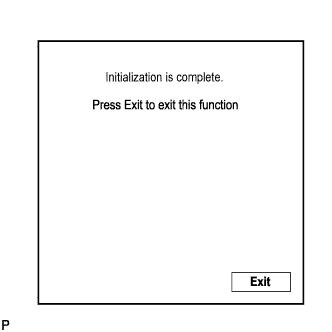
When the screen indicating reset completion is displayed, push "Exit".
-
-
A/F SENSOR COMPENSATION RESET FUNCTION
-
This procedure uses the GTS to perform "A/F Sensor Compensation Reset".
-
When replacing the A/F sensor, replace the sensor and then perform "A/F Sensor Compensation Reset".
Tech Tips
-
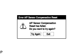
If an error occurs during compensation reset, check the vehicle condition, and then perform compensation reset again.
-
A communication malfunction may occur if there is a problem with the ECM, a wire harness or the connection to the DLC3. If the wire harnesses and the connection to the DLC3 are inspected and found to be normal, the ECM may be malfunctioning.
-
Connect the GTS to the DLC3.
-
Turn the ignition switch to ON.
Note
Do not start the engine.
-
Turn the GTS on.
-
Enter the following menus: Powertrain / Engine and ECT / Utility / A/F Sensor Compensation Reset.
-
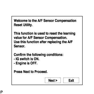
When the first screen is displayed, check the vehicle condition and push "Next".
-
When the screen indicating reset completion is displayed, push "Exit".
-
-
-
REGISTRATION RELATED TO ECD SYSTEM (for 1KD-FTV, w/o DPF)
-
LEARNING VALUES CONFIRMATION
This procedure uses the GTS to display the learned values (injector compensation code, pilot quantity learning value and crank time compensation learning value) stored in the ECM.
Tech Tips
-
A malfunction may occur when reading the values if there is a problem with the ECM, a wire harness or the connection to the DLC3. If the wire harnesses and the connection to the DLC3 are inspected and found to be normal, the ECM may be malfunctioning.
-
Connect the GTS to the DLC3.
-
Turn the ignition switch to ON and turn the GTS on.
Note
Do not start the engine.
-
Enter the following menus: Powertrain / Engine and ECT / Utility / Learning values confirmation.
-
Press "Next".
-
Press "Next" again to proceed.
-
Select the value to confirm and press "Next".
-
When the next screen is displayed, confirm the contents and press "Exit".
-
-
LEARNING VALUES SAVE
This procedure uses the GTS to save the learned values (injector compensation code, pilot quantity learning value and crank time compensation learning value) stored in the ECM in the GTS depending on the components being replaced.

Tech Tips
-
When replacing the engine assembly or the injector assembly together with the ECM, this function automatically determines the data which can be transferred (old data) and saves the data in the GTS.
-
When there is no data to read from the ECM, manually perform the procedure to register each compensation code and learning value in the ECM.
-
A malfunction may occur when reading the values if there is a problem with the ECM, a wire harness or the connection to the DLC3. If the wire harnesses and the connection to the DLC3 are inspected and found to be normal, the ECM may be malfunctioning.
-
Connect the GTS to the DLC3.
-
Turn the ignition switch to ON and turn the GTS on.
Note
Do not start the engine.
-
Enter the following menus: Powertrain / Engine and ECT / Utility / Learning values save.
-
Press "Next".
-

Press "Next" again to proceed.
-
Select any components being replaced and press "Next". If no applicable components are displayed, press "Next" without selecting anything.
-
If the overwrite confirmation screen is displayed, press "Overwrite".
-
When the operation is finished, confirm the date and time of the save operation, and then press "Exit".
-
-
LEARNING VALUES WRITE
This procedure uses the GTS to write all of the learned values (injector compensation code, pilot quantity learning value and crank time compensation learning value) stored in the GTS to the ECM.
Tech Tips
-
A malfunction may occur when writing the values if there is a problem with the ECM, a wire harness or the connection to the DLC3. If the wire harnesses and the connection to the DLC3 are inspected and found to be normal, the ECM may be malfunctioning.
-
Connect the GTS to the DLC3.
-
Turn the ignition switch to ON and turn the GTS on.
Note
Do not start the engine.
-
Enter the following menus: Powertrain / Engine and ECT / Utility / Learning values write.
-
Press "Next".
-
Press "Next" again to proceed.
-
If the "Error Learning Values Write" screen indicating a problem with the saved values or that there are no saved values is displayed, perform "Learning Values Save" again.
-
Confirm the date and time of the save operation, and then press "Yes".
-
Confirm the contents, and then press "Next".
-
If any instructions are displayed on the GTS, manually perform the procedure to register each applicable compensation code or learning value in the ECM.
-
Clear the DTCs.
-
-
INPUT INJECTOR COMPENSATION CODE(S) INTO ECM
Note
-
When an injector assembly is replaced, the new injector compensation code must be input into the ECM. When the ECM is replaced, all of the existing injector compensation codes must be input into the new ECM.
-
Injector compensation codes are unique, 30-digit, alphanumeric values printed on the head portion of each injector assembly. If an incorrect injector compensation code is input into the ECM, the engine assembly may rattle or engine idling may become rough. In addition, engine failure may occur and the life of the engine may be shortened.
-
When an injector compensation code is input into the ECM, the pilot quantity learning values stored in the ECM are initialized. Also, DTC P1601 is stored when the pilot quantity learning values are initialized.
-
After replacing one or more injectors assembly with new ones, input the compensation codes of the injector assemblies into the ECM as follows:
Tech Tips
-
Each injector assembly has different fuel injection characteristics. In order to optimize the fuel injections, the ECM uses the compensation codes to balance the different fuel injections between each injector assembly.
-
When one or more injector assemblies are replaced, input the injector compensation codes, perform pilot quantity learning, and then clear the DTCs.
-
When the ignition switch is turned to ON after replacing the ECM, DTC P1601 is stored. This indicates that one or more injector compensation codes need to be registered. Manually clear the DTC upon completion of pilot quantity learning.
-
Input the compensation codes, which are imprinted on the head portions of the new injector assemblies, into the GTS.
-
Input the new compensation codes into the ECM using the GTS.
-
Turn the GTS off and turn the ignition switch off.
-
Wait for at least 30 seconds.
-
Turn the ignition switch to ON and turn the GTS on.
-
Perform pilot quantity learning.
-
Clear DTC P1601 stored in the ECM using the GTS.
Note
If the DTCs are cleared without performing pilot quantity learning, DTC P1601 is stored immediately after clearing DTCs.
-
-
Register compensation codes.
-
Connect the GTS to the DLC3.
-
Turn the ignition switch to ON.
Note
Do not start the engine.
-
Turn the GTS on.
-
Enter the following menus: Powertrain / Engine and ECT / Utility / Injector Compensation.
-
Press "Next".
-
Press "Next" again to proceed.
-
Select "Set Compensation Code".
-
Press "Next".
-
Select the number of the cylinder corresponding to the injector compensation code that you want to register.
-
Press "Next".
-
Register compensation code.
-
Press "Input".
-
Manually input the cylinder compensation code using the keyboard on the GTS screen. The code is a 30-digit, alphanumeric value printed on the head portion of the injector assembly.
Tech Tips
Each injector compensation code is unique. The compensation code for each selected cylinder must be input into the GTS correctly.
-
Confirm that the compensation code for the selected cylinder is correct, and then press "OK".
-
Check that the compensation code displayed on the screen is correct by comparing it with the 30-digit alphanumeric value on the head portion of the injector assembly.
Note
If an incorrect injector compensation code is input into the ECM, the engine may rattle or engine idling may become rough. In addition, engine failure may occur and the life of the engine may be shortened.
Tech Tips
-
If an incorrect compensation code is input or read, return to the "Input Value" screen by pressing "Input".
-
The saving process may fail due to a problem with the wire harness or a bad connection with the DLC3. Check the wire harness and DLC3 connection. If no problem is found with either, the ECM may be malfunctioning. Check the ECM and repeat this operation.
-
-
Press "Next" to register the compensation code in the ECM.
Tech Tips
-
If the registration process fails, the compensation code may be incorrect. Check the compensation code again.
-
If the input compensation code fails to register even though it is input correctly, there may be a problem with the wire harness or a bad connection with the DLC3. Check the wire harness and DLC3 connection. If no problem is found with either, the ECM may be malfunctioning. Check the ECM and restart this operation.
-
-
If you want to continue with other compensation code registrations, press "Next". To finish the registration, press "Exit".
-
Turn the ignition switch off, and then turn the GTS off.
-
Wait for at least 30 seconds.
-
Turn the ignition switch to ON, and then turn the GTS on.
-
Perform pilot quantity learning.
-
Clear DTC P1601 stored in the ECM using the GTS.
Note
If the DTCs are cleared without performing pilot quantity learning, DTC P1601 is stored immediately after clearing DTCs.
-
-
-
PILOT QUANTITY LEARNING
-
"Pilot Quantity Learning" is performed when injector assemblies have been replaced and injector compensation codes have been registered. "Pilot Quantity Learning (Detail)" is performed when there are engine problems but no DTCs are output and the technician wishes to clear the learned values and have the vehicle relearn the values.
-
This procedure uses the GTS to perform "Pilot Quantity Learning".
-
When replacing the injector assembly, engine or ECM, perform this procedure after performing injector compensation (manual ID code registration).
Note
After completing this procedure, clear the DTCs using the GTS.
Tech Tips
-
If "Exit" is pushed during the step where the accelerator pedal is operated and "Pilot Quantity Learning" is canceled, turn the ignition switch off, wait 10 seconds, check the vehicle condition, and then perform learning again.
-
If an error occurs during learning, check the vehicle condition after turning the ignition switch off, and then perform learning again.
-
If learning is canceled and DTCs are output due to excessive racing of the engine (depressing the accelerator pedal for 2 seconds or more), turn the ignition switch off, and then perform learning again.
-
A communication malfunction may occur if there is a problem with the ECM, a wire harness or the connection to the DLC3. If the wire harnesses and the connection to the DLC3 are inspected and found to be normal, the ECM may be malfunctioning.
-
Connect the GTS to the DLC3.
-
Start the engine.
-
Turn the GTS on.
-
Enter the following menus: Powertrain / Engine and ECT / Utility / Pilot quantity learning.
-
Press "Next".
-
Press "Next" again to proceed.
-
Confirm that the atmospheric pressure screen is displayed.
-
Confirm the displayed atmospheric pressure.
Standard Atmosphere Pressure is 89 kPa or more Note
-
If the atmospheric pressure is below the standard range, "Pilot Quantity Learning" cannot be performed. In this case, press "Exit" and clear the learned values using "Pilot Quantity Learning Value Clear".
-
If the atmospheric pressure is below the standard range, even if "Pilot Quantity Learning" is performed, learning will not be completed.
-
-
If the atmospheric pressure is within the standard range, proceed to the next screen.
-
-
Confirm the condition of the engine and wait until learning can be performed.
Essential Conditions for Learning Tester Display Standard Coolant Temp 50 to 100°C Intake Air 10 to 120°C Fuel Temperature 25 to 96°C Battery Voltage 10 V or higher Reju Pilot Quantity Learning READY Tech Tips
-
If the values deviate from the standard above, "Pilot Quantity Learning" enters a standby state or is canceled.
-
When the essential conditions to perform learning are met, the screen will change automatically.
Note
-
Using the GTS, make sure that DTCs other than DTC P1601 are not output.
-
If DTCs other than DTC P1601 are output, perform troubleshooting for those DTCs.
Tech Tips
DTC P1601 is stored when the value registered in the ECM for an input injector compensation code and/or pilot quantity deterioration learning value is the initial value.
-
-
Follow the prompts on the screen and repeat the following procedure until the screen changes: Starting with the engine idling, race the engine until the engine speed is 3000 rpm or more for no more than 2 seconds, and then let the engine return to idling.
Tech Tips
-
After confirming that the engine speed has reached 3000 rpm, completely release the accelerator pedal in order for the throttle opening amount to become 0%.
-
It is possible to confirm the status of the learning operation during "Pilot Quantity Learning" by observing the blinking pattern of the glow indicator light.
Glow Indicator Light Blinking Pattern Learning Status Glow Indicator Light Condition Conditions essential to start learning have not been met Blinking at 0.5 second intervals Conditions essential to start learning have been met Blinking at 1 second intervals During racing (learning is being performed) Blinking at 1 second intervals Learning is finished Off Learning has been canceled Blinking at 1.5 second intervals Learning has been canceled (malfunctioning cylinder is indicated by blinking pattern) Blinking at 0.8 second intervals (2.3 second intervals between each set of blinks representing the number of a malfunctioning cylinder) 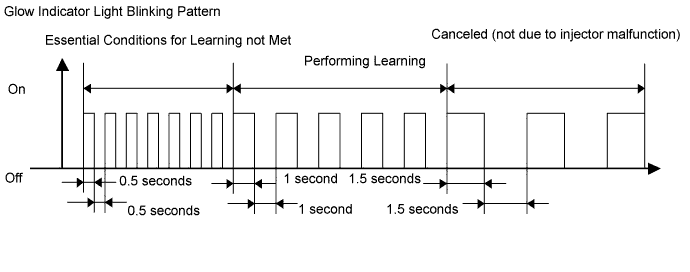
-
-
When the screen changes, push "Exit".
-
Turn the ignition switch off, and then turn the GTS off.
-
Wait for at least 10 seconds.
-
Turn the ignition switch to ON, and then turn the GTS on.
-
Clear the DTCs.
-
Turn the ignition switch off.
Note
Do not disconnect the cable from the negative (-) battery terminal for 30 seconds after turning the ignition switch off.
Tech Tips
-
The main relay turns off after the learned value is stored in the ECM.
-
The main relay turns off within approximately 5 to 10 seconds of turning the ignition switch off.
-
-
-
PILOT QUANTITY LEARNING (DETAIL)
-
"Pilot Quantity Learning" is performed when injector assemblies have been replaced and injector compensation codes have been registered. "Pilot Quantity Learning (Detail)" is performed when there are engine problems but no DTCs are output and the technician wishes to clear the learned values and have the vehicle relearn the values.
It takes time to clear the learned values and perform learning for all cylinders.
-
This procedure uses the GTS to perform "Pilot Quantity Learning (Detail)".
-
When replacing the injector assembly, engine or ECM, perform this procedure after performing injector compensation (manual ID code registration).
Note
After completing this procedure, clear the DTCs using the GTS.
Tech Tips
-
If "Exit" is pushed during the step where the accelerator pedal is operated and "Pilot Quantity Learning (Detail)" is canceled, turn the ignition switch off, wait 10 seconds, check the vehicle condition, and then perform learning again.
-
If an error occurs during learning, check the vehicle condition after turning the ignition switch off, and then perform learning again.
-
If learning is canceled and DTCs are output due to excessive racing of the engine (depressing the accelerator pedal for 2 seconds or more), turn the ignition switch off, and then perform learning again.
-
A communication malfunction may occur if there is a problem with the ECM, a wire harness or the connection to the DLC3. If the wire harnesses and the connection to the DLC3 are inspected and found to be normal, the ECM may be malfunctioning.
-
Connect the GTS to the DLC3.
-
Start the engine.
-
Turn the GTS on.
-
Enter the following menus: Powertrain / Engine and ECT / Utility / Pilot quantity learning (Detail).
-
Press "Next".
-
Press "Next" again to proceed.
-
Confirm that the atmospheric pressure screen is displayed.
-
Confirm the displayed atmospheric pressure.
Standard Atmosphere Pressure is 89 kPa or more Note
-
If the atmospheric pressure is below the standard range, "Pilot Quantity Learning" cannot be performed. In this case, press "Exit" and clear the learned values using "Pilot Quantity Learning Value Clear".
-
If the atmospheric pressure is below the standard range, even if "Pilot Quantity Learning" is performed, learning will not be completed.
-
-
If the atmospheric pressure is within the standard range, proceed to the next screen.
-
-
Confirm the condition of the engine and wait until learning can be performed.
Essential Conditions for Learning Tester Display Standard Coolant Temp 50 to 100°C Intake Air 10 to 120°C Fuel Temperature 25 to 96°C Battery Voltage 10 V or higher Reju Pilot Quantity Learning READY Tech Tips
-
If the values deviate from the standard above, "Pilot Quantity Learning (Detail)" enters a standby state or is canceled.
-
When the essential conditions to perform learning are met, the screen will change automatically.
Note
-
Using the GTS, make sure that DTCs other than DTC P1601 are not output.
-
If DTCs other than DTC P1601 are output, perform troubleshooting for those DTCs.
Tech Tips
DTC P1601 is stored when the value registered in the ECM for an input injector compensation code and/or pilot quantity deterioration learning value is the initial value.
-
-
Follow the prompts on the screen and repeat the following procedure until the screen changes: Starting with the engine idling, race the engine until the engine speed is 3000 rpm or more for no more than 2 seconds, and then let the engine return to idling.
Tech Tips
-
After confirming that the engine speed has reached 3000 rpm, completely release the accelerator pedal in order for the throttle opening amount to become 0%.
-
It is possible to confirm the status of the learning operation during "Pilot Quantity Learning (Detail)" by observing the blinking pattern of the glow indicator light.
Glow Indicator Light Blinking Pattern Learning Status Glow Indicator Light Condition Conditions essential to start learning have not been met Blinking at 0.5 second intervals Conditions essential to start learning have been met Blinking at 1 second intervals During racing (learning is being performed) Blinking at 1 second intervals Learning is finished Off Learning has been canceled Blinking at 1.5 second intervals Learning has been canceled (malfunctioning cylinder is indicated by blinking pattern) Blinking at 0.8 second intervals (2.3 second intervals between each set of blinks representing the number of a malfunctioning cylinder)
-
-
When the screen changes, push "Exit".
-
Turn the ignition switch off, and then turn the GTS off.
-
Wait for at least 10 seconds.
-
Turn the ignition switch to ON, and then turn the GTS on.
-
Clear the DTCs.
-
Turn the ignition switch off.
Note
Do not disconnect the cable from the negative (-) battery terminal for 30 seconds after turning the ignition switch off.
Tech Tips
-
The main relay turns off after the learned value is stored in the ECM.
-
The main relay turns off within approximately 5 to 10 seconds of turning the ignition switch off.
-
-
-
PILOT QUANTITY LEARNING VALUE CLEAR
Tech Tips
-
If the atmospheric pressure is below the threshold value, "Pilot Quantity Learning" will not be completed and DTC P1601 is stored. After "Pilot Quantity Learning Value Clear" is performed, DTC P1601 will not be stored.
-
Clear the learned values using the following procedure.
-
Connect the GTS to the DLC3.
-
Turn the ignition switch to ON, and then turn the GTS on.
-
Enter the following menus: Powertrain / Engine and ECT / Utility / Pilot Quantity Learning Value Clear
-
Press "Next".
-
Confirm that the atmospheric pressure screen is displayed.
-
Confirm the displayed atmospheric pressure.
Standard Atmosphere Pressure is below 89 kPa Note
-
If the atmospheric pressure is higher than the standard range for performing "Pilot Quantity Learning Value Clear", do not clear the learned values. Instead, perform "Pilot Quantity Learning".
-
When the atmospheric pressure is higher than the standard range, perform "Pilot Quantity Learning" without initializing the learned values using "Pilot Quantity Learning Value Clear". If the learned values are initialized when the atmospheric pressure is higher than the standard range, the following symptoms may appear. Be sure to correctly follow procedures.
-
Driveability problems
-
Rough idle
-
Emission of white or black smoke, etc.
-
-
Proceed to the next screen.
-
-
Select the cylinders whose learned value will be cleared.
Note
-
Multiple cylinders can be selected.
-
Only the cylinders for which fuel injector compensation codes have been written must have their learned value cleared.
-
-
After selecting the cylinders whose learned value will be cleared, press "Next" to begin the initialization.
-
When the screen changes, push "Exit".
-
Turn the ignition switch off, and then turn the GTS off.
-
Wait for at least 10 seconds.
-
Turn the ignition switch to ON, and then turn the GTS on.
-
Clear the DTCs.
-
Turn the ignition switch off and leave the vehicle for 30 seconds or more.
-
Turn the ignition switch to ON for 1 second.
-
Enter the following menus: Powertrain / Engine and ECT / DTC.
-
Read the DTCs.
-
Confirm that no DTCs are output.
-
-
-
INITIALIZATION RELATED TO ECD SYSTEM (for 1KD-FTV, w/o DPF)
-
SUPPLY PUMP INITIALIZATION PROCEDURE
Tech Tips
After replacing the supply pump and/or ECM:
-
If the engine is defective or stalls immediately after startup, the learned values of the ECM must be initialized. The engine can be initialized through the GTS or by connecting DLC3 terminals.
-
If the engine starts normally, initialization is not necessary. Perform the steps labeled procedure "A" and procedure "B" only.
-
Connect the GTS to the DLC3.
-
Turn the ignition switch to ON.
Note
Do not start the engine.
-
Turn the GTS on.
-
Enter the following menus: Powertrain / Engine and ECT / Utility / Supply Pump Initialization.
-
Press "Next".
-
Press "Next".
-
Press "Exit".
-
Start the engine to check if the initialization is complete. If the engine cannot be started, repeat the initialization procedures from the beginning (Procedure "A").
-
Idle the engine for at least 1 minute under the following conditions: (Procedure "B")
-
The engine coolant temperature is 60°C (140°F) or higher.
-
The fuel temperature is 20°C (68°F) or higher.
Note
Do not race the engine immediately after starting the engine. After warming up the engine, racing the engine is acceptable.
Tech Tips
-
The engine coolant temperature can be estimated by touching the outlet hose.
-
The fuel temperature can be estimated by using the ambient temperature as a substitute.
-
If the engine coolant temperature is difficult to estimate, use the GTS and enter the following menus: Powertrain / Engine and ECT / Data List / Coolant Temp.
-
-
Initialization is complete.
-
-
CRANK TIME COMPENSATION RESET FUNCTION
-
This procedure uses the GTS to perform "Crank Time Compensation Reset".
-
When replacing the timing rotor (engine assembly), perform "Crank Time Compensation Reset".
Tech Tips
-
If an error occurs during compensation reset, check the vehicle condition, and then perform compensation reset again.
-
A communication malfunction may occur if there is a problem with the ECM, a wire harness or the connection to the DLC3. If the wire harnesses and the connection to the DLC3 are inspected and found to be normal, the ECM may be malfunctioning.
-
Connect the GTS to the DLC3.
-
Turn the ignition switch to ON.
Note
Do not start the engine.
-
Turn the GTS on.
-
Enter the following menus: Powertrain / Engine and ECT / Utility / Crank Time Compensation Reset.
-
When the first screen is displayed, check the vehicle condition and push "Next".
-
When the screen indicating reset completion is displayed, push "Exit".
-
-
-
REGISTRATION RELATED TO ECD SYSTEM (for 2KD-FTV)
-
LEARNING VALUES CONFIRMATION
This procedure uses the GTS to display the learned values (injector compensation code, pilot quantity initial learning value, pilot quantity deterioration learning value, pilot quantity current learning value, pilot quantity learning value, crank time compensation learning value, A/F sensor learning value and catalyst deterioration learning value) stored in the ECM.
Tech Tips
-
A malfunction may occur when reading the values if there is a problem with the ECM, a wire harness or the connection to the DLC3. If the wire harnesses and the connection to the DLC3 are inspected and found to be normal, the ECM may be malfunctioning.
-
Connect the GTS to the DLC3.
-
Turn the ignition switch to ON and turn the GTS on.
Note
Do not start the engine.
-
Enter the following menus: Powertrain / Engine and ECT / Utility / Learning values confirmation.
-
Press "Next".
-
Press "Next" again to proceed.
-
Select the value to confirm and press "Next".
-
When the next screen is displayed, confirm the contents and press "Exit".
-
-
LEARNING VALUES SAVE
This procedure uses the GTS to save the learned values (injector compensation code) stored in the ECM in the GTS depending on the components being replaced.
Tech Tips
-
When replacing the engine assembly, injector assembly together with the ECM, this function automatically determines the data which can be transferred (old data) and saves the data in the GTS.
-
When there is no data to read from the ECM, manually perform the procedure to register each compensation code and learning value in the ECM.
-
A malfunction may occur when reading the values if there is a problem with the ECM, a wire harness or the connection to the DLC3. If the wire harnesses and the connection to the DLC3 are inspected and found to be normal, the ECM may be malfunctioning.
-
Connect the GTS to the DLC3.
-
Turn the ignition switch to ON and turn the GTS on.
Note
Do not start the engine.
-
Enter the following menus: Powertrain / Engine and ECT / Utility / Learning values save.
-
Press "Next".
-
Press "Next" again to proceed.
-
Select any components being replaced and press "Next". If no applicable components are displayed, press "Next" without selecting anything.
-
If the overwrite confirmation screen is displayed, press "Overwrite".
-
When the operation is finished, confirm the date and time of the save operation, and press "Exit".
-
-
LEARNING VALUES WRITE
This procedure uses the GTS to write all of the learned values (injector compensation code) stored in the GTS to the ECM.
Tech Tips
-
A malfunction may occur when writing the values if there is a problem with the ECM, a wire harness or the connection to the DLC3. If the wire harnesses and the connection to the DLC3 are inspected and found to be normal, the ECM may be malfunctioning.
-
Connect the GTS to the DLC3.
-
Turn the ignition switch to ON and turn the GTS on.
Note
Do not start the engine.
-
Enter the following menus: Powertrain / Engine and ECT / Utility / Learning values write.
-
Press "Next".
-
Press "Next" again to proceed.
-
If the "Error Learning Values Write" screen indicating a problem with the saved value(s) or that there are no saved values is displayed, perform "Learning Values Save" again.
-
Confirm the date and time of the save operation, and then press "Yes".
-
Confirm the contents, and then press "Next".
-
If any instructions are displayed on the GTS, manually perform the procedure to register each applicable compensation code or learning value in the ECM.
-
Clear the DTCs.
-
-
AFTER REPLACING INJECTOR(S) WITH NEW ONE(S), INPUT COMPENSATION CODE(S) OF INJECTOR(S) INTO ECM AS FOLLOWS:
Note
-
When an injector is replaced, the injector's compensation code must be input into the ECM. When the ECM is changed, all of the existing injector compensation codes must be input into the new ECM.
-
Injector compensation codes are unique, 30-digit, alphanumeric values printed on the head portion of each injector. If an incorrect injector compensation code is input into the ECM, the engine may rattle or engine idling may become rough. In addition, engine failure may occur and the life of the engine may be shortened.
-
Connect the GTS to the DLC3.
-
Turn the ignition switch ON.
-
Turn the GTS ON.
Note
Do not start the engine.
Tech Tips
The injector compensation code is imprinted on the head portion of each injector.
-
Enter the menu options in this order: Power train / Engine / Utility / Injector Compensation.
-
Press Next.
-
Press Next again to proceed.
-
Select "Set Compensation Code".
-
Press Next.
-
Select the number of the cylinder corresponding to the injector compensation code that you want to read.
-
Press Next.
-
Register compensation code.
-
Press input.
-
Manually input the cylinder's compensation code using the keyboard on the GTS screen. The code is a 30-digit, alphanumeric value imprinted on the injector's head portion.
Tech Tips
Each injector compensation code is unique. The correct compensation code must be input into each cylinder selected on the GTS.
-
Confirm that the compensation code is correct for the selected cylinder is correct , and then press OK.
-
-
Check that the compensation code displayed on the screen is correct, by comparing it with the 30-digit alphanumeric value on the head portion of the injector.
Note
If an incorrect injector compensation code was input into the ECM, the engine may rattle or engine idling may become rough. In addition, engine failure may occur and the life of the engine may be shortened.
Tech Tips
If a wrong compensation code was input or read, return to the input Value screen by pressing input. The saving process may fail due to a problem with the wire harness or a bad connection with the DLC3. Check the wire harness and the DLC3 connection. If no problem is found with either, the ECM may be malfunctioning. Check the ECM and repeat this operation.
-
Press Next to set the compensation code to the ECM.
Tech Tips
-
If the setting process fails, the compensation code may be incorrect. Check the compensation code again.
-
If the attempted compensation code is correct, a problem with the wire harness or a bad connection with the DLC3 may cause the failure. Check the wire harness and the DLC3 connection. If no problem is found with either, the ECM may be malfunctioning. Check the ECM and restart this operation.
-
-
If you want to continue with other compensation code registrations, press Next. To finish the registration, press Cancel.
-
Turn the GTS OFF and then turn the ignition switch OFF.
-
Wait for at least 30 seconds.
-
Turn the ignition switch ON and then turn the GTS ON.
-
Clear DTC P1601 stored in the ECM using the GTS.
-
-
WHEN REPLACING ECM WITH NEW ONE, INPUT ALL INJECTOR'S COMPENSATION CODES INTO NEW ECM AS FOLLOWS:
Note
-
When an injector is replaced, the injector's compensation code must be input into the ECM. When the ECM is changed, all of the existing injector compensation codes must be input into the new ECM.
-
Injector compensation codes are unique, 30-digit, alphanumeric values printed on the head portion of each injector. If an incorrect injector compensation code is input into the ECM, the engine may rattle or engine idling may become rough. In addition, engine failure may occur and the life of the engine may be shortened.
Tech Tips
The following operation is available with ECMs that can transmit the registered injector compensation codes to the GTS.
-
Connect the GTS to the DLC3.
-
Turn the ignition switch ON.
-
Turn the GTS ON.
Note
Do not start the engine.
Tech Tips
The injector compensation code is imprinted on the head portion of each injector.
-
Enter the menu options in this order: Power train / Engine / Utility / Injector Compensation.
-
Press Next.
-
Press Next again to proceed.
-
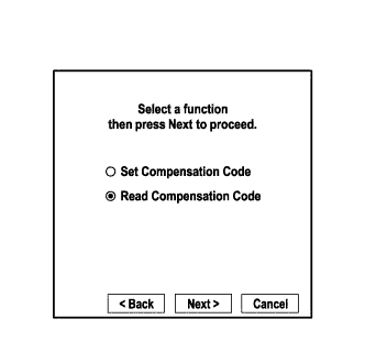
Select Read Compensation Code.
-
Press Next.
-
Select the number of the cylinder corresponding to the injector compensation code that you want to read.
-
Press Next.
Tech Tips
The reading process may fail due to a problem with the wire harness or a bad connection with the DLC3. Check the wire harness and the DLC3 connection. If no problem is found, the ECM may be malfunctioning. Check the ECM and restart this operation.
-
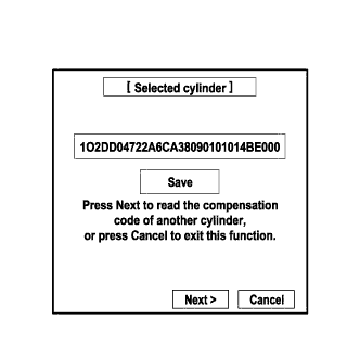
Check the injector compensation code (30-digit alphanumeric value) is displayed on the GTS screen.
-
Press Save.
-
Check that the compensation code displayed on the GTS screen is correct.
-
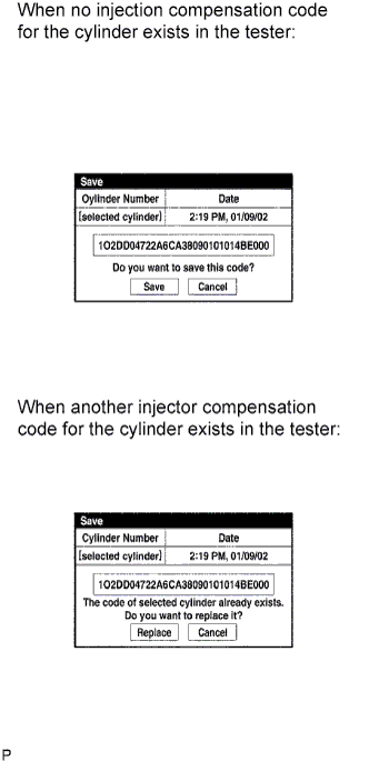
Press Save or Replace, save the injector compensation code.
Tech Tips
-
The existing compensation code is overwritten with the new compensation code and is deleted from the GTS.
-
The saving process may fail due to a problem with the wire harness or a bad connection with the DLC3. Check the wire harness and the DLC3 connection. If no problem is found with either, the ECM may be malfunctioning. Check the ECM and restart this operation.
-
-
If you want to read and save other injector compensation codes for other cylinders, press Next to continue. To finish this operation, press Cancel.
-
Turn the ignition switch OFF.
-
Turn the GTS OFF.
-
Replace the ECM.
-
Connect the GTS to the DLC3.
-
Turn the ignition switch ON.
-
Turn the GTS ON.
Note
Do not start the engine.
Tech Tips
The injector compensation code is imprinted on the head portion of each injector.
-
Enter the menu options in this order: Power train / Engine / Utility / Injector Compensation.
-
Press Next.
-
Press Next again to proceed.
-
Select Set Compensation Code.
-
Press Next.
-
Select the number of the cylinder corresponding to the injector compensation code that you want to read.
-
Press Next.
-
Check that the compensation code displayed on the screen is correct, by comparing it with the 30-digit alphanumeric value on the head portion of the injector.
Note
If an incorrect injector compensation code was input into the ECM, the engine may rattle or engine idling may become rough. In addition, engine failure may occur and the life of the engine may be shortened.
Tech Tips
If a wrong compensation code was input or read, return to the input Value screen by pressing input. The saving process may fail due to a problem with the wire harness or a bad connection with the DLC3. Check the wire harness and the DLC3 connection. If no problem is found with either, the ECM may be malfunctioning. Check the ECM and repeat this operation.
-
Press Next to set the compensation code to the ECM.
Tech Tips
-
If the setting fails, the compensation code may be incorrect. Check the compensation code again.
-
If the attempted compensation code is correct, a problem with the wire harness or a bad connection with the DLC3 may cause the failure. Check the wire harness and the DLC3 connection. If no problem is found with either, the ECM may be malfunctioning. Check the ECM and restart this operation.
-
-
If you want to continue with other compensation code registrations, press Next. To finish the registration, press Cancel.
-
Turn the GTS OFF and then turn the ignition switch OFF.
-
Wait for at least 30 seconds.
-
Turn the ignition switch ON and then turn the GTS ON.
-
Clear DTC P1601 stored in the ECM using the GTS.
-
-
-
INITIALIZATION RELATED TO ECD SYSTEM (for 2KD-FTV)
Tech Tips
When the diesel throttle body assembly or electric EGR control valve assembly is replaced, perform initialization
-
DIESEL THROTTLE BODY ASSEMBLY AND ELECTRIC EGR CONTROL VALVE ASSEMBLY INITIALIZATION PROCEDURE
Tech Tips
control valve assembly is replaced, perform initialization
-
Turn the ignition switch to ON.
Note
Do not start the engine.
-
Turn the ignition switch off and wait for 30 seconds or more.
-
Turn the ignition switch to ON and wait for 10 seconds or more.
-
-
SUPPLY PUMP INITIALIZATION PROCEDURE
Tech Tips
-
If the engine is defective or stalls immediately after startup, the learned values of the ECM must be initialized. The engine can be initialized through the GTS or by connecting DLC3 terminals.
-
If the engine starts normally, initialization is not necessary. Perform the steps labeled procedure "A" and procedure "B" only.
After replacing the supply pump and/or ECM:
-
Connect the GTS to the DLC3.
-
Turn the ignition switch to ON.
Note
Do not start the engine.
-
Turn the GTS on.
-
Enter the following menus: Powertrain / Engine and ECT / Utility / Supply Pump Initialization.
-
Press "Next".
-
Press "Next".
-
Press "Exit".
-
Start the engine to check if the initialization is complete. If the engine cannot be started, repeat the initialization procedures from the beginning (Procedure "A").
-
Idle the engine for at least 1 minute under the following conditions: (Procedure "B")
-
The engine coolant temperature is 60°C (140°F) or higher.
-
The fuel temperature is 20°C (68°F) or higher.
Note
Do not race the engine immediately after starting the engine. After warming up the engine, racing the engine is acceptable.
Tech Tips
-
The engine coolant temperature can be estimated by touching the outlet hose.
-
The fuel temperature can be estimated by using the ambient temperature as a substitute.
-
If the engine coolant temperature is difficult to estimate, use the GTS and enter the following menus: Powertrain / Engine and ECT / Data List / Coolant Temp.
-
-
Initialization is complete.
-
-
-
REGISTRATION RELATED TO ENGINE CONTROL SYSTEM (for 2TR-FE)
CAUTION:
The Vehicle Identification Number VIN) must be input into a replacement ECM.
Tech Tips
The VIN is a 17-digit alphanumeric vehicle identification number. The GTS is required to register the VIN.
-
DESCRIPTION
Tech Tips
This registration section consists of two parts: Read VIN and Write VIN.
-
Read VIN: This process allows the VIN stored in the ECM to be read in order to confirm that the two VINs, the one provided with the vehicle and the one stored in the vehicle's ECM, are the same.
-
Write VIN: This process allows the VIN to be input into the ECM. If the ECM is changed, or the ECM VIN and vehicle VIN do not match, the VIN can be registered or overwritten in the ECM by following this procedure.
-
-
READ VIN
-
Confirm the vehicle VIN.
-
Connect the intelligent tester to the DLC3.
-
Turn the ignition switch to ON.
-
Turn the intelligent tester on.
-
Enter the following menus: Powertrain / Engine and ECT / Utility / VIN / VIN Read.
-
-
WRITE VIN
-
Confirm the vehicle VIN.
-
Connect the intelligent tester to the DLC3.
-
Turn the ignition switch to ON.
-
Turn the intelligent tester on.
-
Enter the following menus: Powertrain / Engine and ECT / Utility / VIN / VIN Write.
-
-
-
PERFORM INITIALIZATION (for 1TR-FE )
Note
-
Be sure to perform this procedure after reassembling the throttle body assembly or removing and reinstalling any throttle body component.
-
Perform the following procedure after replacing the ECM, throttle body assembly or any throttle body components. The following procedure should also be performed if the throttle body is cleaned.
-
Be sure to perform this procedure after reconnecting the battery cable or replacing the ECM.
-
Disconnect the EFI No. 2 fuse and ETCS fuse at the same time. Wait at least 60 seconds and reconnect the fuses.
-
Turn the ignition switch to ON without operating the accelerator pedal.
Note
If the accelerator pedal is operated, perform the above steps again.
-
Connect the intelligent tester to the DLC3 and clear the DTCs.
-
Start the engine and check that the MIL is not illuminated. After the engine is warmed up, check that the idle speed is within the specified range when the A/C is switched off.
Note
-
Be sure to perform this step with all accessories off.
-
Make sure that the shift lever is in N or P.
-
-
Enter the following menus: Powertrain / Engine and ECT / Data List / All Data / Throttle Sensor Position. Fully depress the accelerator pedal and check that the value is 60% or more.
-
Perform a road test and confirm that there are no abnormalities.
-
-
INITIALIZATION RELATED LIGHTING SYSTEM
Note
-
When the conditions shown in the table below are met, it is necessary to perform vehicle information registration or initialization for the headlight leveling ECU assembly.
-
Adjust the headlight aim after initializing the headlight leveling ECU.
Operation Performed Necessary Procedure Proceed to The headlight leveling ECU assembly is replaced with a new one. Headlight leveling ECU assembly initialization Proceed to step 1 or step 2 The vehicle height changes due to replacement of suspension components or after performing such operations as removal and reinstallation or replacement of the rear height control sensor sub-assembly LH. Headlight leveling ECU assembly initialization Proceed to step 1 or step 2
-
HEADLIGHT LEVELING ECU ASSEMBLY INITIALIZATION (USING GTS)
Tech Tips
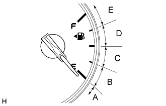
Initialization for the headlight leveling ECU assembly is performed based on the fuel level, which is divided into 5 levels, indicated by the needle of the fuel receiver gauge.
-
Check the vehicle condition.
-
Put the vehicle in the following condition:
-
Vehicle is unloaded (except spare tire and spare tire tools, etc.).
-
No occupants other than the driver are in the vehicle.
-
Headlights are turned off.
-
Vehicle is stopped and vehicle height remains constant (vehicle is on a level surface and stable).
Tech Tips
If the above conditions are not met, initialization cannot be performed normally.
-
-
Check the warning indicator in the multi-information display.
-
Check the warning indicator in the multi-information display 6 seconds after turning the ignition switch from off to ON.
Standard Condition Specified Condition Headlight leveling ECU assembly initialization malfunction Warning indicator blinks 6 times at 2 Hz continuously Removal/installation or replacement of the rear height control sensor sub-assembly LH, replacement of the suspension, etc. Warning indicator is not illuminated Tech Tips
If the warning indicator condition is not as specified, check the wire harness(es) and connector(s) of the headlight leveling ECU assembly.
-
-
Initialization procedure
-
-
Connect the GTS to the DLC3 with the ignition switch off.
-
Turn the ignition switch to ON.
-
Enter the following menus: Body Electrical / HL AutoLeveling / Utility / Height Sensor Initialization.
-
Check what is displayed on the screen of the GTS and press "Next".
-
The appropriate position ID is determined by the fuel level (remaining amount of fuel) of the fuel receiver gauge as shown in the chart below.
Fuel Level Position ID Number of Times Warning Indicator Blinks (N) Fuel level is within range A. EMPTY 1 Fuel level is within range B. EMPTY to 1/4 full 2 Fuel level is within range C. 1/4 to 1/2 full 3 Fuel level is within range D. 1/2 to 3/4 full 4 Fuel level is within range E. 3/4 to FULL 5 -
Input the position ID determined by the chart above into the GTS and press "Next".
-
Check the warning indicator in the multi-information display.
Standard Condition Specified Condition Headlight leveling ECU assembly initialization malfunction Blinks 6 times at 2 Hz → Blinks N* times at 2 Hz continuously (initialization completes normally) Removal/installation or replacement of the rear height control sensor sub-assembly LH, replacement of the suspension, etc. Off → Blinks N* times at 2 Hz continuously (initialization completes normally) Tech Tips
-
*: Refer to the chart above for N.
-
If the warning indicator condition in the multi-information display does not change, perform the procedure from the beginning once again.
-
If the warning indicator illuminates continuously, there may be a malfunction in the headlight leveling ECU assembly.
-
-
Check that initialization has completed normally, and then turn the ignition switch off.
Tech Tips
The blinking warning indicator that indicates that initialization has completed normally continues until the ignition switch is turned off.
-
-
-
HEADLIGHT LEVELING ECU ASSEMBLY INITIALIZATION (WITHOUT USING GTS)
Tech Tips
Initialization for the headlight leveling ECU assembly is performed based on the fuel level, which is divided into 5 levels, indicated by the needle of the fuel receiver gauge.
-
Check the vehicle condition.
-
Put the vehicle in the following condition:
-
Vehicle is unloaded (except spare tire and spare tire tools, etc.).
-
No occupants other than the driver are in the vehicle.
-
Headlights are turned off.
-
Vehicle is stopped and vehicle height remains constant (vehicle is on a level surface and stable).
Tech Tips
If the above conditions are not met, initialization cannot be performed normally.
-
-
Check the warning indicator in the multi-information display.
-
Check the warning indicator in the multi-information display 6 seconds after turning the ignition switch from off to ON.
Standard Condition Specified Condition Headlight leveling ECU assembly initialization malfunction Warning indicator blinks 6 times at 2 Hz continuously Removal/installation or replacement of the rear height control sensor sub-assembly LH, replacement of the suspension, etc. Warning indicator is not illuminated Tech Tips
If the warning indicator condition is not as specified, check the wire harness(es) and connector(s) of the headlight leveling ECU assembly.
-
-
Initialization procedure
-
-
Turn the ignition switch to ON.
-
The number of times the headlight dimmer switch operates is determined by the fuel level (remaining amount of fuel) of the fuel receiver gauge as shown in the chart below.
Tech Tips
The number of times the switch is operated is necessary in a later procedure.
Fuel Level Number of Times Switch is Operated (N) Fuel level is within range A. 1 Fuel level is within range B. 2 Fuel level is within range C. 3 Fuel level is within range D. 4 Fuel level is within range E. 5 -
Enter initialization mode.
-
Turn the ignition switch to ON with the headlight dimmer switch off.
-
Turn the headlight dimmer switch from off to the HEAD position and back off 3 times or more with the headlight dimmer switch in the high-beam flash condition.
-
Turn the headlight dimmer switch off
Tech Tips
-
Perform the above operation within 5 seconds.
-
When initialization mode has been entered, the warning indicator in the multi-information display starts blinking at 1 Hz.
-
-
After entering initialization mode, turn the low beam headlights from off to on and back off again N* times.
Tech Tips
-
*: The number of times to turn the headlight dimmer switch on and off (N) is determined by the fuel level of the fuel receiver gauge.
-
Turn the headlight dimmer switch on and off within 20 seconds of entering initialization mode.
-
Turn the headlight dimmer switch on and off at intervals of approx. 3 seconds.
-
-
Check the warning indicator in the multi-information display 3 seconds after the headlight dimmer switch is operated.
Standard Condition Specified Condition Headlight leveling ECU assembly initialization malfunction Blinks 6 times at 2 Hz → Blinks N* times at 2 Hz continuously (initialization completes normally) Removal/installation or replacement of the rear height control sensor sub-assembly LH, replacement of the suspension, etc. Off → Blinks N* times at 2 Hz continuously (initialization completes normally) Tech Tips
-
*: N is the number of times that the headlight dimmer switch has been operated.
-
If the warning indicator condition in the multi-information display does not change, perform the procedure from the beginning once again after turning the ignition switch off.
-
If the warning indicator illuminates continuously, there may be a malfunction in the headlight leveling ECU assembly.
-
-
Check that initialization has completed normally, and then turn the ignition switch off.
Tech Tips
The blinking warning indicator that indicates that initialization has completed normally continues until the ignition switch is turned off.
-
-
-
-
REGISTRATION RELATED TO WIRELESS DOOR LOCK CONTROL SYSTEM (w/o Smart Entry and Start System)
Tech Tips
-
If replacing the door control transmitter or the door control receiver, register its recognition code to the body ECU.
-
The add mode is used to register new recognition codes while still retaining codes already registered. This mode is used when a new transmitter is added. If the number of registered codes exceeds 6, the previously registered codes will be erased in order, starting from the oldest registered code.
-
The rewrite mode is used to erase all the previously registered recognition codes in order to register all-new recognition codes. This mode is used when the transmitter or the door control receiver is replaced.
-
The confirmation mode is used to confirm how many recognition codes have already been registered before another recognition code is registered.
-
The prohibition mode is used to erase all the registered codes and disable the wireless door lock function. This mode is used when the transmitter is lost.
-
All of the following registration procedures must be performed in order.
-
PROCEDURE FOR RECOGNITION CODE REGISTRATION
-
The following conditions should be met before starting the procedure:
-
No key is in the ignition key cylinder.
-
Only driver side door is open.
-
-
Insert the key into the ignition key cylinder, then pull it out (Procedure "A").
-
Insert the key into the ignition key cylinder, then pull it out within 5 seconds after procedure "A" (Procedure "B").
-
Close and open the driver side door twice.
-
Insert the key into the ignition key cylinder, then pull it out within 40 seconds after procedure "B" (Procedure "C").
-
Close and open the driver side door twice.
-
Insert the key into the ignition key cylinder and close all doors within 40 seconds after procedure "C" (Procedure "D").
-
Turn the ignition switch from the LOCK to the ON position and back to the LOCK position at approximately 1 second intervals according to the number of times shown in the table below.
Number of ON-LOCK operations of ignition switch: Mode Selection Ignition Switch ON-LOCK Operation Ignition Key Position Add mode Once 
-
A: Ignition switch position "ON"
-
B: Ignition switch position "LOCK"
-
T1: Approximately 1 second.
Rewrite Mode Twice 
-
A: Ignition switch position "ON"
-
B: Ignition switch position "LOCK"
-
T1: Approximately 1 second.
Confirmation Mode 3 times 
-
A: Ignition switch position "ON"
-
B: Ignition switch position "LOCK"
-
T1: Approximately 1 second.
Prohibition Mode 5 times 
-
A: Ignition switch position "ON"
-
B: Ignition switch position "LOCK"
-
T1: Approximately 1 second.
-
-
Remove the key from the ignition key cylinder within 40 seconds after the procedure "D" (Procedure "E").
-
The body ECU automatically performs power door LOCK-UNLOCK operations to indicate which mode has been selected.
Tech Tips
If the number of ON-LOCK operations of the ignition switch is 0, 4 or 6 or more, there will be no response (power door LOCK-UNLOCK operation).
Response to selected mode (Power door lock operation): Mode Selection Power Door Lock LOCK-UNLOCK Door Lock Status Add mode 1 cycle 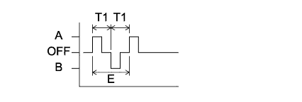
-
A: Door lock motor status "LOCK"
-
B: Door lock motor status "UNLOCK"
-
E: 1 cycle
-
T1: Approximately 1 second
Rewrite Mode 2 cycles 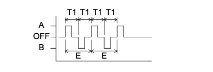
-
A: Door lock motor status "LOCK"
-
B: Door lock motor status "UNLOCK"
-
E: 1 cycle
-
T1: Approximately 1 second
Confirmation Mode The number of registered codes (1 to 4 cycles) 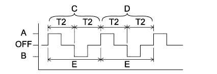
-
A: Door lock motor status "LOCK"
-
B: Door lock motor status "UNLOCK"
-
C: 1st time
-
D: 2nd time
-
E: 1 cycle
-
T2: Approximately 2 seconds
Prohibition Mode 5 cycles 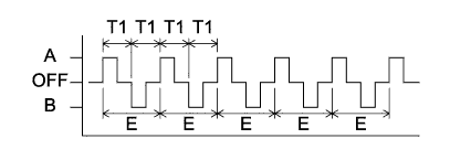
-
A: Door lock motor status "LOCK"
-
B: Door lock motor status "UNLOCK"
-
E: 1 cycle
-
T1: Approximately 1 second
Tech Tips
-
In confirmation mode, LOCK-UNLOCK operation will occur once for each recognition code that has been registered. For example, if 2 recognition codes have been registered, LOCK-UNLOCK movement will occur twice.
-
In confirmation mode, if no recognition codes have been registered, LOCK-UNLOCK operation will occur 11 times.
-
-
Press both LOCK and UNLOCK switches on the transmitter simultaneously for 1 second or more. (Procedure F).
-
Press either LOCK or UNLOCK switch for 1 second or more within 45 seconds after performing procedure E.
-
The body ECU automatically performs power door LOCK-UNLOCK operations to indicate whether registration has been completed correctly.
Response to registration completion: Power Door Lock LOCK-UNLOCK Operation Result Door Lock Status 1 cycle Registration of recognition code has been completed.
-
A: Door lock motor status "LOCK"
-
B: Door lock motor status "UNLOCK"
-
E: 1 cycle
-
T1: Approximately 1 second
2 cycles Registration of recognition code has failed.
-
A: Door lock motor status "LOCK"
-
B: Door lock motor status "UNLOCK"
-
E: 1 cycle
-
T1: Approximately 1 second
Tech Tips
If registration of recognition code has failed, perform registration procedures again from the beginning.
Tech Tips
*1: All 6 recognition codes can be registered consecutively.
-
-
Perform either of the following:
-
Open a door.
-
Insert the key into the ignition key cylinder.
-
-
Registration of recognition codes (add mode and rewrite mode) is completed.
-
-
-
INITIALIZATION RELATED TO POWER WINDOW CONTROL SYSTEM
-
RESET (INITIALIZE) POWER WINDOW REGULATOR MOTOR
Note
-
Resetting the power window motor (initializing the pulse sensor) is necessary when the battery terminal is disconnected; when the power window master switch, power window regulator switch, wire harness, power window regulator and power window motor are replaced or removed/installed; or when the POWER fuse and DOOR fuse are replaced. AUTO operation function, jam protection function and remote operation function via the power window master switch do not operate without resetting.
-
Be sure to reset the power window regulator motors using the power window switch on each door because the motors cannot be reset by remote operation using the power window master switch.
-
In order to prevent a large amount of current from flowing in the wires, do not simultaneously reset 2 or more power window regulator motors.
-
If the power window switch has been continuously operated for a long time, the power window regulator motor will stop so that no additional load will be applied to the motor. Continuing to operate the switch even after the motor has stopped will cause the switch to blink while restricting the AUTO UP/DOWN function and the remote UP/DOWN function. If this happens, reset the motor again after several minutes have passed.
-
Whenever disconnecting the battery terminal, reset all the other systems besides the power window control system.
-
Turn the ignition switch ON.
-
Halfway open the power window by pressing the power window switch.
-
Fully pull up the switch until the power window is fully closed and continue to hold the switch for approximately 1 second after the power window is fully closed.
-
Check that the AUTO UP/DOWN function operates normally.
If the AUTO UP/DOWN function operates normally, reset operations have been completed at this time. If not normal, follow steps below.
-
Disconnect the negative battery terminal for 10 seconds.
-
Connect the battery terminal.
-
Turn the ignition switch ON.
-
Halfway open the power window by pressing the power window switch.
-
If the AUTO UP/DOWN function operates normally, reset operations have been completed at this time.
If not normal, follow steps below.
-
Turn the ignition switch ON.
-
Halfway open the power window by pressing the power window switch.
-
Fully pull up the switch until the power window is fully closed and continue to hold the switch for approximately 12 seconds after the power window is fully closed.
-
Check that the AUTO UP/DOWN function operates normally.
-
-
-
-
INITIALIZATION RELATED TO POWER SLIDE DOOR SYSTEM
-
RESET SLIDE DOOR CLOSED POSITION
-
When disconnecting the cable from the battery terminal, close the slide door fully.
Tech Tips
If the slide door is closed when disconnecting the cable from the battery terminal, it is not necessary to reset it.
-
-