ENGINE ASSEMBLY INSTALLATION

-
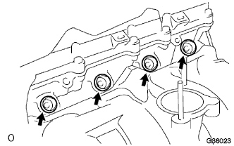
INSTALL ENGINE OIL LEVEL SENSOR
-
Install the engine oil level sensor with the 4 bolts.
- Torque:
- 7.0 N*m { 71 kgf*cm, 52 in.*lbf }
-
-
INSTALL ENGINE MOUNTING BRACKET FRONT NO.1 LH
-
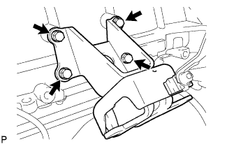
Install the mounting bracket with the 4 bolts.
- Torque:
- 51 N*m { 520 kgf*cm, 38 ft.*lbf }
-
-
INSTALL ENGINE MOUNTING BRACKET FRONT NO.1 RH
-
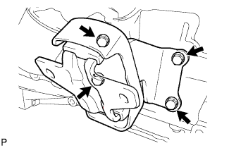
Install the mounting bracket with the 4 bolts.
- Torque:
- 51 N*m { 520 kgf*cm, 38 ft.*lbf }
-
-
INSTALL WATER TEMPERATURE SENSOR
-
Using a 19 mm deep socket wrench, install a new gasket and the water temperature sensor.
- Torque:
- 20 N*m { 204 kgf*cm, 15 ft.*lbf }
-
-
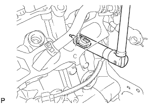
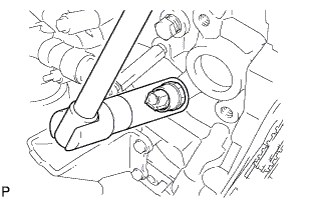
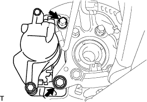
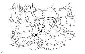
INSTALL KNOCK CONTROL SENSOR
-
Install the bolt and knock control sensor as shown in the illustration.
- Torque:
- 20 N*m { 204 kgf*cm, 15 ft.*lbf }
-
Connect the knock control sensor connector.
-
-
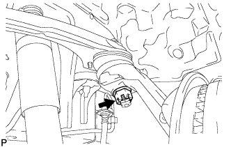
INSTALL ENGINE OIL PRESSURE SWITCH ASSEMBLY
-
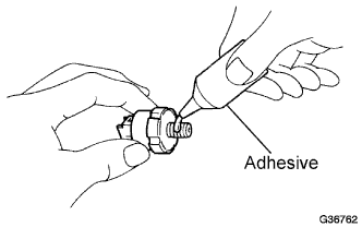
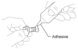
Apply adhesive to 2 or 3 threads of the oil pressure switch.
Adhesive Toyota Genuine Adhesive 1344, Three Bond 1344 or equivalent -
Install the oil pressure switch.
- Torque:
- 15 N*m { 153 kgf*cm, 11 ft.*lbf }
Note
Do not start the engine for at least 1 hour after installation of the switch.
-
-
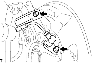
INSTALL V-RIBBED BELT TENSIONER ASSEMBLY
-
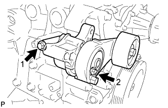
Temporarily install the belt tensioner with the 2 bolts.
Tech Tips
-
Make sure that the belt tensioner is in contact with the engine block.
-
Check that the bolt holes of the belt tensioner and timing chain cover are aligned.
-
-
Install the tensioner by tightening the 2 bolts in the order shown in the illustration.
- Torque:
- Bolt 1
- 40 N*m { 408 kgf*cm, 30 ft.*lbf }
- Bolt 2
- 21 N*m { 214 kgf*cm, 15 ft.*lbf }
-
-
INSTALL IDLER PULLEY SUB-ASSEMBLY NO.1
-
Install the idler pulley sub-assembly No.1, collar and pulley plate with the bolt.
- Torque:
- 43 N*m { 438 kgf*cm, 32 ft.*lbf }
Note
Check that the pulley plate and collar are assembled properly to the idler pulley No.1.
-
-
INSTALL COMPRESSOR MOUNTING BRACKET NO.1 (w/ Air Conditioning System)
-
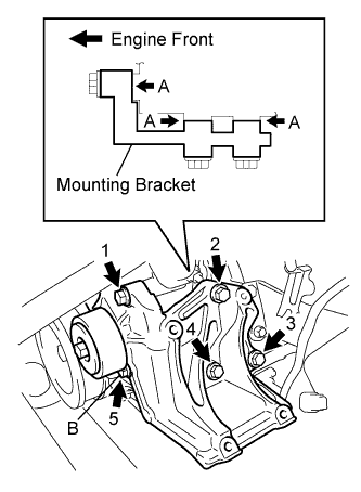
Temporarily install the mounting bracket with the 5 bolts.
Tech Tips
Make sure that the mounting bracket is in contact with the engine block at points A shown in the illustration.
-
Install the mounting bracket by tightening the 5 bolts in the order shown in the illustration.
- Torque:
- Bolt B
- 25 N*m { 255 kgf*cm, 18 ft.*lbf }
- Except bolt B
- 45 N*m { 459 kgf*cm, 33 ft.*lbf }
Note
In order to prevent misalignment, which causes belt rattle, tightening of the bolts must be performed in the order shown.
-
-
INSTALL GENERATOR ASSEMBLY
-
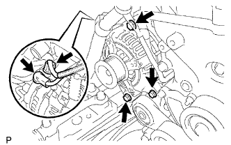
Install the generator assembly with the 3 bolts.
- Torque:
- 43 N*m { 438 kgf*cm, 32 ft.*lbf }
-
Install the generator wire with the nut to terminal B.
- Torque:
- 9.8 N*m { 100 kgf*cm, 87 in.*lbf }
-
Install the terminal cap.
-
Connect the generator connector.
-
-
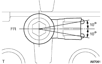
INSTALL THERMOSTAT
-
Install a new gasket to the thermostat.
-
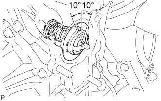
Install the thermostat with the jiggle valve upward.
Tech Tips
The jiggle valve may be set within 10° of either side of the prescribed position.
-
-
INSTALL WATER INLET
-
Install a new gasket and the water inlet with the bolt and 2 nuts.
- Torque:
- 28 N*m { 286 kgf*cm, 21 ft.*lbf }
-
-
INSTALL WATER BY-PASS PIPE NO.1
-
Install a new gasket and the water by-pass pipe with the 2 nuts and bolt.
- Torque:
- Nut
- 18 N*m { 180 kgf*cm, 13 ft.*lbf }
- Bolt
- 8.0 N*m { 80 kgf*cm, 71 in.*lbf }
-
-
INSTALL FAN PULLEY
-
Install the fan spacer and fan pulley with the 4 nuts.
- Torque:
- 25 N*m { 255 kgf*cm, 18 ft.*lbf }
-
-
INSTALL EXHAUST MANIFOLD
-
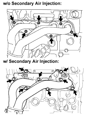
w/o Secondary air injection system:
-
Install a new gasket and the exhaust manifold with the new 6 nuts.
- Torque:
- 36 N*m { 367 kgf*cm, 27 ft.*lbf }
-
-
w/ Secondary air injection system:
-
Install a new gasket and the exhaust manifold with the new 8 nuts.
- Torque:
- 36 N*m { 367 kgf*cm, 27 ft.*lbf }
-
-
-
INSTALL AIR SWITCHING VALVE ASSEMBLY (w/ Secondary Air Injection System)
-
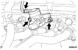
Install the valve with the 2 new nuts.
- Torque:
- 20 N*m { 204 kgf*cm, 15 ft.*lbf }
-
Connect the connector.
-
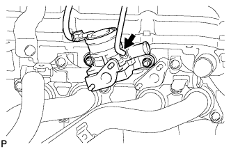
w/ Manifold Absolute Pressure Sensor:
Connect the vacuum hose to the air switching valve assembly.
-
-
INSTALL INTAKE PIPE NO.4 (w/ Secondary Air Injection System)
-
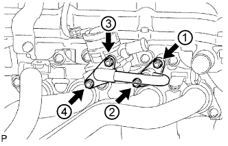
Install 2 new gaskets and the intake pipe No.4 with 4 new nuts and tighten the nuts in the order shown in the illustration. Then, tighten the nuts labeled 1 and 3 to the torque specification again.
- Torque:
- 20 N*m { 204 kgf*cm, 15 ft.*lbf }
-
Check that the nuts are tightened to the torque specification.
Note
Tightening the nuts only once is not enough to tighten them to the torque specification.
-
-
INSTALL EXHAUST MANIFOLD HEAT INSULATOR NO.1
-
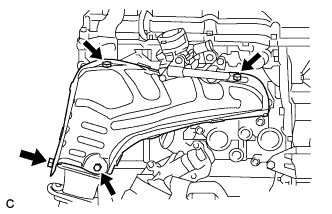
Install the heat insulator with the 4 bolts.
- Torque:
- 12 N*m { 122 kgf*cm, 9 ft.*lbf }
-
-
INSTALL INJECTOR ASSEMBLY
-
Apply a light coat of grease or gasoline to new O-rings and install them to the injector spacers.
Note
Make sure that the O-rings are installed between the parts correctly.
-
Install the injection spacers.
-
Apply a light coat of grease or gasoline to the place where the delivery pipe touches the O-ring.
-
To install the fuel injector into the fuel delivery pipe, push the fuel injector while twisting it right and left.
Note
-
Be careful not to twist the O-ring.
-
After installing the fuel injector, check that it turns smoothly. If not, reinstall it with a new O-ring.
-
-
-
INSTALL FUEL DELIVERY PIPE SUB-ASSEMBLY
-
Install the 4 spacers to the cylinder head.
-
Install the delivery pipe spacers.
-
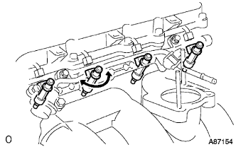
Temporarily install the 2 bolts and fuel delivery pipe together with the 4 injectors.
Note
-
Do not drop the fuel injector when installing the fuel delivery pipe.
-
Make sure that the fuel injector turns smoothly.
-
-
Fully tighten the 2 bolts.
- Torque:
- 12 N*m { 122 kgf*cm, 10 ft.*lbf }
-
Apply a light coat of grease or gasoline to the place where the delivery pipe touches the O-ring.
-
Install the 2 bolts and pressure pulsation damper assembly.
- Torque:
- 8.5 N*m { 87 kgf*cm, 75 in.*lbf }
-
Connect the 2 fuel hoses.
-
-
INSTALL SPARK PLUG
- Torque:
- 18 N*m { 184 kgf*cm, 13 ft.*lbf }
-
INSTALL IGNITION COIL ASSEMBLY
-
Install the ignition coils with the bolts.
- Torque:
- 9.0 N*m { 92 kgf*cm, 80 in.*lbf }
-
-
INSTALL INTAKE MANIFOLD
-
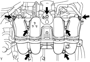
Install a new gasket and the intake manifold with the 5 bolts and 2 nuts.
- Torque:
- 25 N*m { 255 kgf*cm, 18 ft.*lbf }
-
Connect the ventilation hose No.3.
-
-
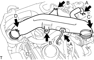
INSTALL THROTTLE WITH MOTOR BODY ASSEMBLY
-
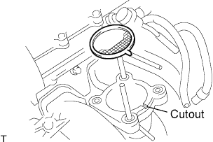
Install a new gasket onto the intake manifold.
Tech Tips
Fit the gasket to the cutout of the intake manifold.
-
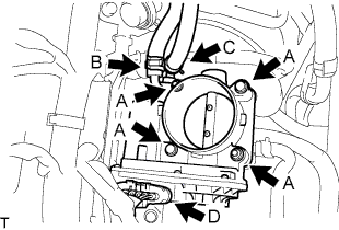
Install the throttle body assembly with the 2 bolts and 2 nuts. (A)
- Torque:
- 9.0 N*m { 92 kgf*cm, 80 in.*lbf }
-
Connect the water by-pass hose. (B)
-
Connect the water by-pass hose No.2. (C)
-
Connect the throttle motor connector. (D)
-
-
INSTALL VENTILATION PIPE
-
Install the ventilation pipe with the bolt.
- Torque:
- 18 N*m { 184 kgf*cm, 13 ft.*lbf }
-
-
INSTALL ENGINE WIRE
-
Install the engine wire to the engine assembly.
-
-
REMOVE ENGINE STAND
-
INSTALL FRONT SUSPENSION CROSS MEMBER SUB-ASSEMBLY
-
Install the engine assembly to the cross member.
-
Connect the engine mounting insulator with the 4 bolts.
- Torque:
- 55 N*m { 561 kgf*cm, 41 ft.*lbf }
-
-
INSTALL REAR END PLATE
-
Install the rear end plate with the 2 bolts.
- Torque:
- 18 N*m { 184 kgf*cm, 13 ft.*lbf }
-
-
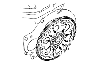
INSTALL FLYWHEEL SUB-ASSEMBLY (for Manual Transmission)
Tech Tips
If any one of the mounting bolts is broken or deformed, replace it.
-
Apply adhesive to 2 or 3 threads of the mounting bolt end.
Adhesive Toyota Genuine Adhesive 1324, Three Bond 1324 or equivalent -
Install the flywheel.
-

Fix the crankshaft with SST.
- SST
- 09213-54015 ( 91651-60855 )
- 09330-00021
-
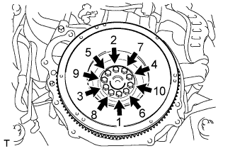
Install and uniformly tighten the 10 mounting bolts in several steps in the sequence shown in the illustration.(*1)
- Torque:
- 27 N*m { 276 kgf*cm, 20 ft.*lbf }
If any one of the mounting bolts does not meet the torque specification, replace the mounting bolt.
-
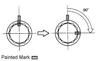
Mark the mounting bolt with paint.(*2)
-
Retighten the mounting bolt by 90° in the order shown in step (*1).
-
Check that the painted mark is now at a 90° angle to that in step (*2).
-
-
INSTALL CLUTCH DISC ASSEMBLY (for Manual Transmission)
-
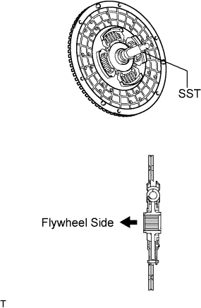
Insert SST into the clutch disc assembly, then insert them into the flywheel sub-assembly.
- SST
- 09301-00110
Note
Take care not to insert the clutch disc assembly in the wrong direction.
-
-
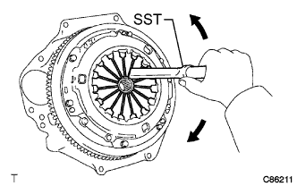
INSTALL CLUTCH COVER ASSEMBLY (for Manual Transmission)
-
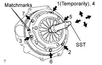
Align the matchmark on the clutch cover assembly with the one on the flywheel sub-assembly.
-
Following the procedures shown in the illustration, tighten the 6 bolts starting from the bolt located near the knock pin on the top.
- SST
- 09301-00110
- Torque:
- 19 N*m { 195 kgf*cm, 14 ft.*lbf }
Tech Tips
-
Evenly tighten the bolts by following the order shown in the illustration.
-
Tighten the bolts after checking that the disc is in the center by lightly moving the SST up and down, left and right.
-
-
INSPECT AND ADJUST CLUTCH COVER ASSEMBLY (for Manual Transmission)
-
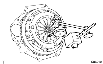
Using a dial indicator with a roller instrument, check the diaphragm spring tip alignment.
Maximum non-alignment 0.9 mm (0.035 in.) -
If alignment is not as specified, adjust the diaphragm spring tip alignment using SST.
- SST
- 09333-00013
-
-
INSTALL DRIVE PLATE AND RING GEAR SUB-ASSEMBLY (for Automatic Transmission)
-
Apply adhesive to 2 or 3 threads of the mounting bolt end.
Adhesive Toyota Genuine Adhesive 1324, Three Bond 1324 or equivalent -
Install the spacer FR, drive plate and spacer RR on the crankshaft.
Note
Do not start the engine for at least 1 hour after installing.
-
Fix the crankshaft with SST.
- SST
- 09213-54015 ( 91651-60855 )
- 09330-00021
-
Install and uniformly tighten the 10 mounting bolts in several steps in the sequence shown in the illustration.
- Torque:
- 74 N*m { 750 kgf*cm, 55 ft.*lbf }
-
-
INSTALL MANUAL TRANSMISSION UNIT ASSEMBLY (for Manual Transmission)
-
INSTALL AUTOMATIC TRANSMISSION ASSEMBLY (for Automatic Transmission)
-
INSTALL STARTER ASSEMBLY (for 1.6 kW Type)
-
Install the starter with the 2 bolts.
- Torque:
- 37 N*m { 377 kgf*cm, 27 ft.*lbf }
-
Connect the wire harness to terminal 30 and install the nut.
- Torque:
- 9.8 N*m { 100 kgf*cm, 87 in.*lbf }
-
Connect the terminal 50 connector to the starter assembly.
-
Install the ground cable and wire bracket with the 2 bolts.
- Torque:
- 25 N*m { 250 kgf*cm, 18 ft.*lbf }
-
-
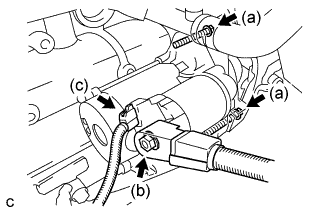
INSTALL STARTER ASSEMBLY (for 1.4 kW Type)
-
Install the starter with the 2 bolts.
- Torque:
- 37 N*m { 377 kgf*cm, 27 ft.*lbf }
-
Connect the starter wire to terminal 30 with the nut.
- Torque:
- 9.8 N*m { 100 kgf*cm, 87 in.*lbf }
-
Install the terminal cap.
-
Connect the starter connector.
-
Connect the ground wire with the bolt.
- Torque:
- 25 N*m { 250 kgf*cm, 18 ft.*lbf }
-
Install the wire harness bracket with the bolt.
- Torque:
- 25 N*m { 250 kgf*cm, 18 ft.*lbf }
-
Attach the wire harness.
-
-
INSTALL ENGINE ASSEMBLY WITH TRANSMISSION
-
Using the engine lifter, hold the engine assembly and install the engine assembly w/ transmission.
-
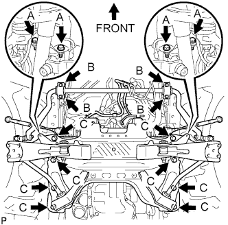
Install the stabilizer bracket and 16 bolts of the front suspension cross member.
- Torque:
- Bolt A
- 39 N*m { 398 kgf*cm, 29 ft.*lbf }
- Bolt B
- 36 N*m { 367 kgf*cm, 27 ft.*lbf }
- Bolt C
- 150 N*m { 1,530 kgf*cm, 111 ft.*lbf }
-
Connect the rear engine mount.
- Torque:
- 98 N*m { 999 kgf*cm, 72 ft.*lbf }
Note
Be sure to tighten the nut side.
-
Remove the engine lifter slowly.
-
-
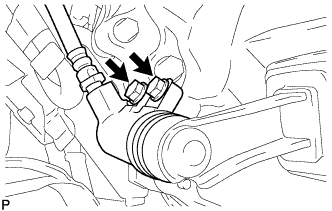
CONNECT STEERING TORQUE SHAFT ASSEMBLY
-
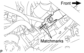
Align the matchmarks on the steering torque shaft assembly and the power steering link assembly.
-
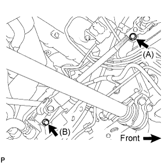
Install bolt (B) and tighten the 2 bolts.
- Torque:
- 35 N*m { 360 kgf*cm, 26 ft.*lbf }
-
-
CONNECT OIL COOLER HOSE (for Automatic Transmission)
-
Connect the oil cooler inlet hose and outlet hose with the clamp to the oil cooler tube.
-
-
CONNECT TRANSMISSION CONTROL CABLE ASSEMBLY (for Automatic Transmission)
-
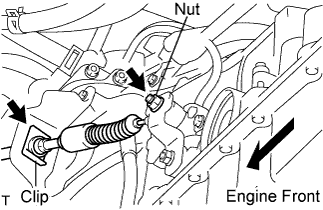
Install the transmission control cable assembly to the control shaft lever and transmission control bracket No.1 with the nut and a new clip.
- Torque:
- 15 N*m { 150 kgf*cm, 11 ft.*lbf }
-
-
INSTALL TRANSMISSION OIL FILLER TUBE SUB-ASSEMBLY (for Automatic Transmission)
-
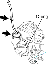
Coat a new O-ring with ATF and install the oil filler tube.
-
Install the oil filler tube with 2 bolts.
- Torque:
- 12 N*m { 125 kgf*cm, 10 ft.*lbf }
-
-
INSTALL TRANSMISSION CONTROL CABLE ASSEMBLY (for Manual Transmission)
-
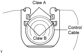
Install 2 new clips to the transmission control cable bracket No.1.
-
Install the transmission control cable assembly to the transmission control cable bracket No.1.
Note
-
Be sure that A claws of the clips are firmly engaged into the bracket grooves.
-
Be sure the cable is set in the clip with both B claws erected to prevent slippage of the cable in the opposite direction.
-
-
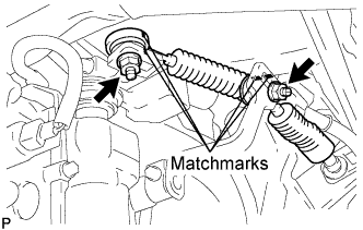
Align the matchmarks on the control cable assembly and the outer lever.
-
Install the transmission control cable assembly to the outer levers with the 2 nuts.
- Torque:
- 37 N*m { 377 kgf*cm, 27 ft.*lbf }
-
-
INSTALL CLUTCH RELEASE CYLINDER ASSEMBLY (for Manual Transmission)
-
Install the clutch release cylinder with the 2 bolts.
- Torque:
- 12 N*m { 120 kgf*cm, 9 ft.*lbf }
-
-
CONNECT SHOCK ABSORBER ASSEMBLY FRONT LH
-
CONNECT SHOCK ABSORBER ASSEMBLY FRONT RH
Tech Tips
Use the same procedures described for the LH side.
-
CONNECT FRONT SUSPENSION SUB-ASSEMBLY UPPER LH
-
Connect the front suspension upper arm to the steering knuckle with the nut.
- Torque:
- 113 N*m { 1,150 kgf*cm, 83 ft.*lbf }
-
Install a new cotter pin.
Note
-
If the holes for the cotter pin are not aligned, tighten the nut up to 60°.
-
Do not damage the ball joint dust cover.
-
-
-
CONNECT FRONT SUSPENSION SUB-ASSEMBLY UPPER RH
Tech Tips
Use the same procedures described for the LH side.
-
INSTALL FRONT DISC BRAKE CALIPER ASSEMBLY LH
-
Install the brake caliper assembly to the steering knuckle with the 2 bolts.
- Torque:
- 123 N*m { 1,250 kgf*cm, 91 ft.*lbf }
-
-
INSTALL FRONT DISC BRAKE CALIPER ASSEMBLY RH
Tech Tips
Use the same procedures described for the LH side.
-
INSTALL SPEED SENSOR FRONT LH (w/ ABS)
-
Install the speed sensor to the steering knuckle with the 2 bolts.
- Torque:
- 8.5 N*m { 87 kgf*cm, 75 in.*lbf }
Note
-
Prevent foreign matter from adhering to the speed sensor.
-
Be careful not to damage the speed sensor.
-
Do not twist the sensor wire when installing the speed sensor.
-
-
INSTALL SPEED SENSOR FRONT RH (w/ ABS)
Tech Tips
Use the same procedures described for the LH side.
-
INSTALL PROPELLER WITH CENTER BEARING SHAFT ASSEMBLY (for Super Long Wheelbase)
-
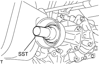
Remove the SST from the extension housing.
-
Install the propeller with center bearing shaft assembly in the extension housing.
-
Install the center support bearing assembly No.1, and temporarily tighten the 2 bolts.
-
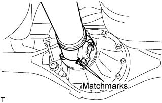
Align the matchmarks on the propeller shaft flange and differential flange.
-
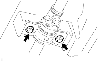
Install the propeller shaft assembly with the 4 nuts, 4 bolts and 4 washers.
- Torque:
- 74 N*m { 755 kgf*cm, 54 ft.*lbf }
-
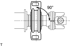
Check that the center line of the bracket is at right angles to the shaft axial direction.
-
Adjust the center support bearing assembly No.1.
Tech Tips
-
With the vehicle unladen, adjust the center support bearing No.1 to maintain the angles, as shown.
-
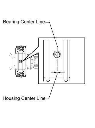
In the same conditions, check the center line in the axial direction. Adjust the bearing if necessary.
-
The center bearing center line and center bearing housing center line must be adjusted to within -1.0 to 1.0 mm (-0.0394 to 0.0394 in.) of each other in the vehicle's longitudinal direction with the vehicle unladen.
-
-
Tighten the 2 bolts.
- Torque:
- 36 N*m { 369 kgf*cm, 27 ft.*lbf }
-
-
INSTALL PROPELLER SHAFT ASSEMBLY (for Long Wheelbase)
-
Remove the SST from the extension housing.
-
Install the propeller shaft assembly in the extension housing.
-
Align the matchmarks on the propeller shaft flange and differential flange.
-
Install the propeller shaft assembly with the 4 nuts, 4 bolts and 4 washers.
- Torque:
- 74 N*m { 755 kgf*cm, 54 ft.*lbf }
-
-
INSTALL EXHAUST PIPE ASSEMBLY CENTER (for Super Long Wheelbase)
-
Install a new gasket to the exhaust pipe assembly center.
-
Connect the exhaust pipe assembly center to the exhaust pipe supports.
-
Install the exhaust pipe assembly center and exhaust pipe assembly tail with the 2 bolts.
- Torque:
- 48 N*m { 489 kgf*cm, 35 ft.*lbf }
-
-
INSTALL EXHAUST PIPE ASSEMBLY FRONT (for Super Long Wheelbase)
-
w/ Secondary air infection system:
-
Install the air fuel ratio sensor. Click here
- Torque:
- 44 N*m { 449 kgf*cm, 32 ft.*lbf }
-
-
For Unleaded gasoline engine:
-
Install the oxygen sensor. Click here
- Torque:
- 44 N*m { 449 kgf*cm, 32 ft.*lbf }
-
-
Inspect the compression spring.
-
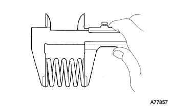
Using vernier calipers, measure the free length of the compression springs.
Minimum length 40.5 mm (1.594 in.) Tech Tips
If the free length is less than the minimum, replace the compression spring.
-
-
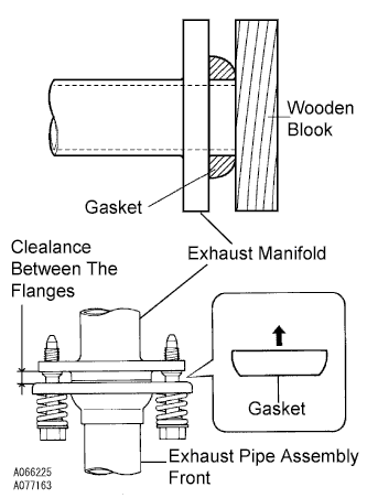
Install the gasket.
-
Fully insert a new gasket to the exhaust manifold by hand.
-
Using a wooden block, uniformly strike the gasket so that the gasket and exhaust manifold are properly fit.
Note
-
Be careful with the installation direction of the gasket.
-
Do not reuse the gasket.
-
Do not damage the gasket.
-
To ensure a proper seal, do not use the exhaust pipe assembly front to force the gasket onto the exhaust manifold.
-
-
Install a new gasket to the exhaust pipe assembly front.
-
Connect the exhaust pipe assembly front to the exhaust pipe support.
-
Install the exhaust pipe assembly front with the 4 bolts, 2 nuts, and 2 compression springs.
- Torque:
- Exhaust manifold side
- 43 N*m { 438 kgf*cm, 32 ft.*lbf }
- Exhaust pipe assembly center side
- 48 N*m { 489 kgf*cm, 35 ft.*lbf }
Note
After installation, check that the clearance is almost the same at any point between the flanges of the exhaust manifold and exhaust pipe assembly front.
-
-
For Unleaded gasoline engine:
-
Connect the sensor connector(s).
-
-
-
INSTALL EXHAUST PIPE ASSEMBLY FRONT (for Long Wheelbase)
-
w/ Secondary air injection system:
-
Install the fuel ratio sensor. Click here
- Torque:
- 44 N*m { 449 kgf*cm, 32 ft.*lbf }
-
-
For unleaded gasoline engine:
-
Install the oxygen sensor. Click here
- Torque:
- 44 N*m { 449 kgf*cm, 32 ft.*lbf }
-
-
Inspect the compression spring.
-
Using vernier calipers, measure the free length of the compression springs.
Minimum length 40.5mm(1.594 in.) Tech Tips
If the free length is less than the minimum, replace the compression spring.
-
-
Install the gasket.
-
Fully insert a new gasket to the exhaust manifold by hand.
-
Using a wooden block, uniformly strike the gasket so that the gasket and exhaust manifold are properly fit.
Note
-
Be careful with the installation direction of the gasket.
-
Do not reuse the gasket.
-
Do not damage the gasket.
-
To ensure a proper seal, do not use the exhaust pipe assembly front to force the gasket onto the exhaust manifold.
-
-
-
Install a new gasket to the exhaust pipe assembly front.
-
Connect the exhaust pipe assembly front to the exhaust pipe support.
-
Install the exhaust pipe assembly front with the 4 bolts, 2 nuts, and 2 compression springs.
- Torque:
- Exhaust manifold side
- 43 N*m { 438 kgf*cm, 32 ft.*lbf }
- Torque:
- Exhaust pipe assembly tail side
- 48 N*m { 489 kgf*cm, 35 ft.*lbf }
Note
After installation, check that the clearance is almost the same at any point between the flanges of the exhaust manifold and exhaust pipe assembly front.
-
For unleaded gasoline engine:
-
Connect the sensor connector(s).
-
-
-
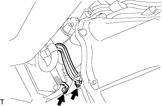
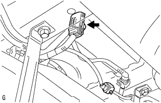
CONNECT ENGINE WIRE
-
Connect the +B terminal and connector of the starter.
- Torque:
- 9.8 N*m { 100 kgf*cm, 87 in.*lbf }
-
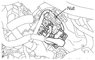
Install the connectors and nut as shown in the illustration.
-
Connect the clamps of the engine wire and earth cable.
-
Connect the connectors of the ECM.
-
Install the wire harness support of the engine ECM.
-
-
INSTALL COMPRESSOR AND MAGNETIC CLUTCH (w/ Air Conditioning System)
-
Temporarily install the bolt A to install the compressor.
-
Install the compressor completely by tightening the 4 bolts in the order shown in the illustration.
- Torque:
- 25 N*m { 255 kgf*cm, 18 ft.*lbf }
Note
In order to prevent misalignment, which causes belt rattle, tightening of the bolts must be performed in the order shown.
-
Connect the suction tube clamp with the bolt.
- Torque:
- 5.4 N*m { 55 kgf*cm, 48 in.*lbf }
-
Connect the compressor connector.
-
-
INSTALL OIL LEVEL GAUGE GUIDE
-
Install the gauge guide with the bolt.
- Torque:
- 20 N*m { 204 kgf*cm, 15 ft.*lbf }
-
-
INSTALL OIL LEVEL GAUGE SUB-ASSEMBLY
-
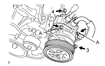
INSTALL VANE PUMP ASSEMBLY
-
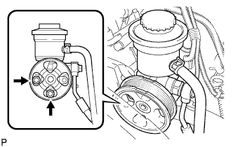
Install the vane pump with the 2 bolts.
- Torque:
- 21 N*m { 214 kgf*cm, 15 ft.*lbf }
-
Connect the PS fluid pressure switch connector.
-
-
CONNECT FUEL HOSE NO.2
-
Connect the fuel hose No.2 to the delivery pipe.
-
-
CONNECT FUEL HOSE
-
Align the connector and pipe. Push on the connector until the retainer locks with a click sound. Click here
-
Pull the connector to check that the connector is securely connected. Click here
-
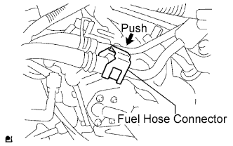
Install the connector and lock it with the fuel hose connector cover. Click here
-
-
CONNECT AIR HOSE NO.5 (w/ Secondary Air Injection System)
-
Connect the air hose No.5 to the air switching valve.
-
-
INSTALL INTAKE AIR CONNECTOR
-
Temporarily install the intake air connector to the throttle body assembly.
-
Connect the ventilation hose No.2 and the vacuum hose. (A)
-
Install the intake air connector with the 2 bolts. (B)
- Torque:
- 8.0 N*m { 82 kgf*cm, 71 in.*lbf }
-
Tighten the 2 hose clamp bolts. (C)
- Torque:
- 5.0 N*m { 51 kgf*cm, 44 in.*lbf }
-
Tighten the 2 hose clamp bolts. (D)
-
-
INSTALL AIR PRESSURE SENSOR (w/ Manifold Absolute Pressure Sensor)
-
Install the air pressure sensor with the bolt.
- Torque:
- 5.0 N*m { 51 kgf*cm, 44 in.*lbf }
-
Install the air pressure sensor together with the bracket with the 2 bolts.
- Torque:
- 8.0 N*m { 82 kgf*cm, 71 in.*lbf }
-
Attach the wire harness clamp.
-
Connect the vacuum hose and clamp.
-
Connect the connector.
-
-
CONNECT UNION TO CONNECTOR TUBE HOSE
-
Connect the union to connector tube hose to the intake manifold.
-
-
CONNECT FUEL VAPOR FEED HOSE ASSEMBLY
-
Connect the fuel vapor feed hose to the VSV.
-
-
CONNECT HEATER WATER HOSE OUTLET B
-
Connect the heater water outlet hose B to the heater unit.
-
-
CONNECT HEATER WATER HOSE INLET A
-
Connect the heater water inlet hose A to the heater unit.
-
-
CONNECT RADIATOR HOSE OUTLET
-
Connect the radiator outlet hose to the clamp.
-
-
CONNECT RADIATOR HOSE INLET
-
Connect the radiator inlet hose to the clamp.
-
-
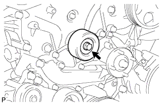
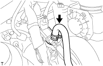
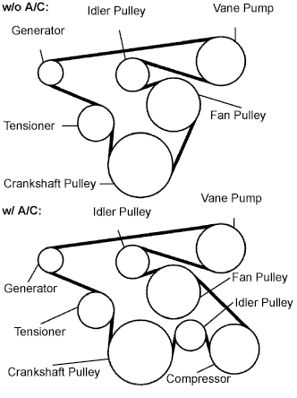
INSTALL FAN & GENERATOR V BELT
-
Install the drive belt to the pulleys except the drive belt tensioner pulley.
-
Use the hexagon-shaped part indicated by the arrow in the illustration to move the tensioner pulley downward and then install the drive belt to the tensioner pulley.
Note
-
The backside of the drive belt should face the tensioner pulley.
-
Check that the drive belt is properly set to each pulley.
-
-
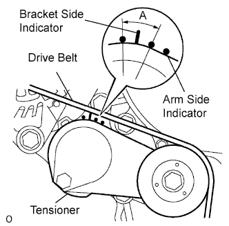
After a new belt has been installed, check that the tensioner indicator mark is within range A shown in the illustration.
-
-
INSTALL ENGINE SERVICE HOLE SUB COVER SUB-ASSEMBLY
-
Install the engine service hole sub cover with the 5 bolts.
- Torque:
- 13 N*m { 133 kgf*cm, 10 ft.*lbf }
-
-
INSTALL FRONT DOOR SCUFF PLATE
-
INSTALL FRONT SEAT ASSEMBLY RH (for Hi-back Seat Type)
-
Perform the same procedure as above on the opposite side. Click here
-
-
INSTALL FRONT SEAT ASSEMBLY RH (for Low-back Seat Type)
-
Perform the same procedure as above on the opposite side. Click here
-
-
INSTALL FRONT WHEELS
- Torque:
- 100 N*m { 1,020 kgf*cm, 74 ft.*lbf }
-
PLACE FRONT WHEELS FACING STRAIGHT AHEAD
-
CONNECT BATTERY NEGATIVE CABLE
-
ADD ENGINE OIL
-
ADD ENGINE COOLANT
-
Firmly tighten the drain plugs and fill the reservoir tank with coolant to the top of the inlet.
-
Remove the 2-way that is located near the throttle body.
-
When air is bled and the coolant drains out, firmly install the 2-way.
-
Add coolant up to the B line mark in the reservoir tank and install the radiator cap.
Coolant Capacity Condition Capacity w/ front and rear heaters 13.6 liters (14.4 US qts, 12.0 lmp. qts) w/ front heater 11.6 liters (12.3 US qts, 10.2 lmp. qts) w/o heater 10.6 liters (11.2 US qts, 9.3 lmp. qts) -
Warm up the engine.
-
After the engine cools down, check that the coolant level is between the LOW and FULL level marks.
-
-
INSPECT FUEL LEAKS
-
When using the intelligent tester
-
Connect the intelligent tester to the DLC3.
-
Turn the ignition switch to the on position and intelligent tester main switch ON.
Note
Do not start the engine.
-
Select the Active Test mode on the intelligent tester.
Tech Tips
Please refer to the intelligent tester operator's manual for further details.
-
-
When not using the intelligent tester.
-
Disconnect the fuel pump connector.
-
Using a service wire, connect terminals FP and +B of the relay block.
Note
Pay attention to the terminal connecting position to avoid a malfunction.
-
Turn the ignition switch to the ON position, and check that the fuel pump operates.
Note
Do not start the engine.
-
-
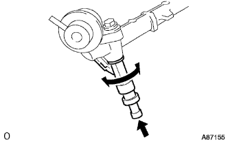
Check that there are no fuel leaks anywhere on the fuel system after doing maintenance.
-
Check that the pulsation damper screw rises up when the fuel pump operates.
If operation is not as specified, check the following parts:
-
Fusible link
-
Fuel pump
-
Wiring connections
-
ECM
-
Fuses
-
-
Turn the ignition switch off.
-
Disconnect the intelligent tester from the DLC3.
-
-
INSPECT ENGINE OIL LEAKS
-
INSPECT MANUAL TRANSMISSION OIL (for Manual Transmission)
-
Park the vehicle in a level place.
-
Remove the transmission filler plug and gasket.
-
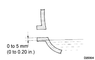
Check that the oil surface is within 5 mm (0.20 in.) below the lowest point of the transmission filler plug opening.
Oil grade GL-4 Viscosity SAE 75W-90 Capacity 2.6 liters (2.7 US qts, 2.3 lmp.qts) Note
-
Problems may occur when the oil level is too high or too low.
-
After replacing the oil, drive the vehicle and check the oil level again.
-
-
Check for oil leakage if the oil level is low.
-
Install the transmission filler plug and a new gasket.
- Torque:
- 37 N*m { 377 kgf*cm, 27 ft.*lbf }
-
-
INSPECT AUTOMATIC TRANSMISSION FLUID (for Automatic Transmission)
Tech Tips
Drive the vehicle so that the engine and transmission are at normal operating temperature.
Fluid temperature 70 to 80 °C (158 to 176 °F)
-
Park the vehicle on a level surface and set the parking brake.
-
With the engine idling and the brake pedal depressed, move shift the lever into all positions from P to L and return to the P position.
-
Take out the dipstick and wipe it clean.
-
Put it back all the way.
-
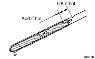
Take it out again and check that the fluid level is within the HOT range.
If the fluid level is below the HOT range, add new fluid and recheck the fluid level. If the fluid level exceeds the HOT range, drain the fluid once, add the proper amount of new fluid and recheck the fluid level.
-
-
INSPECT ENGINE COOLANT LEAKS
CAUTION:
Do not remove the radiator cap while the engine and radiator are still hot. Pressurized, hot engine coolant and steam may be released and cause serious burns.
-
Fill the radiator with coolant and attach a radiator cap tester to the radiator.
-
Warm up the engine.
-
Using a radiator cap tester, increase the pressure inside the radiator to 137 kPa (1.4 kgf/cm2, 19.9 psi), and check that the pressure does not drop.
Tech Tips
If the pressure drops, check the hoses, radiator or water pump for leaks. If no external leaks are found, check the heater core, cylinder block and cylinder head.
-
-
INSPECT SHIFT LEVER POSITION (for Automatic Transmission)
-
When shifting from P position only with ignition switch ON and depress the break pedal.
-
Make sure that the shifting lever moves smoothly and can be moderately operated.
-
When starting engine, make sure that the vehicle moves forward when shifting from N to D position and moves reward when shifting R position.
-
-
ADJUST SHIFT LEVER POSITION (for Automatic Transmission)
-
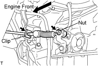
Remove a clip, nut, and disconnect between the control shaft lever to transmission control cable assembly from the control shaft lever and transmission control cable bracket No.1.
-
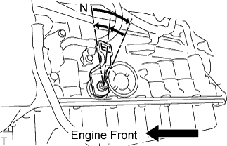
Turn the control shaft lever until stop to a clockwise direction, return the control shaft lever 2 notches to N position.
-

Set the shift lever to N position while holding the shift lever lightly toward the R position side and install it.
- Torque:
- 15 N*m { 150 kgf*cm, 11 ft.*lbf }
Note
Tighten the nut with it closing up cranky.
-
Inspect the operation condition and work.
-
-
INSPECT EXHAUST GAS LEAKS
-
ADJUST FRONT WHEEL ALIGNMENT
-
INSTALL ENGINE SIDE UNDER COVER RH (w/ Engine Side Under Cover RH)
- Torque:
- 13 N*m { 133 kgf*cm, 10 ft.*lbf }
-
INSTALL ENGINE SIDE UNDER COVER LH (w/ Engine Side Under Cover LH)
- Torque:
- 13 N*m { 133 kgf*cm, 10 ft.*lbf }
-
INSTALL ENGINE UNDER COVER NO.2 (w/ Engine Under Cover No.2)
- Torque:
- 13 N*m { 133 kgf*cm, 10 ft.*lbf }
-
INSTALL ENGINE UNDER COVER NO.1 (w/ Engine Under Cover No.1)
- Torque:
- 13 N*m { 133 kgf*cm, 10 ft.*lbf }
-
INSPECT IGNITION TIMING
-
Warm up and stop the engine.
Note
A warmed up engine should have an engine coolant temperature of over 80°C (176°F), have an engine oil temperature of 60°C (140°F), and the engine rpm should be stabilized.
-
When using the intelligent tester:
-
Connect the intelligent tester to the DLC3.
-
Start the engine and idle it.
-
Turn the intelligent tester main switch on.
-
Enter the following items:
Powertrain / Engine and ECT / Data list / IGN Advance
Ignition timing 5 to 15° BTDC at idle Tech Tips
Refer to the intelligent tester operator's manual for further detail.
-
-
When not using the intelligent tester:
-
Connect the tester probe of a timing light to the wire of the ignition coil connector for the No.4 cylinder.
Note
-
Use a timing light that detects the first signal.
-
After checking, be sure to wrap the wire harness with tape.
-
-
Turn the ignition switch to the ON position.
-
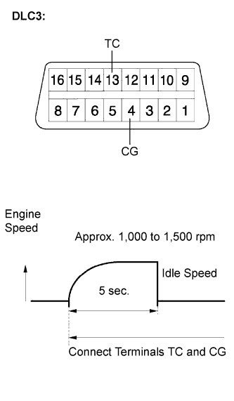
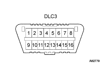
Using SST, connect terminals 13 (TC) and 4 (CG) of the DLC3.
- SST
- 09843-18040
Note
-
Confirm the terminal numbers before connecting them. Connecting the wrong terminals can damage the engine.
-
When checking the ignition timing, the transmission should be in the neutral.
Tech Tips
-
After connecting terminals (TC and CG), engine rpm changes to approximately 1,000 to 1,500 rpm for 5 seconds, then returns to idle speed. This is because the ECM checks that the ISC (idle speed control system) operates properly.
-
Perform the inspection of the ignition timing after engine rpm is returned to idle speed.
-
Inspect the ignition timing
Ignition timing 3 to 7° BTDC at idle -
Disconnect terminals 13 (TC) and 4 (CG) of the DLC3.
-
Inspect the ignition timing
Ignition timing 5 to 15° BTDC at idle -
Check that the ignition timing advances immediately when the engine speed is increased.
-
Turn the ignition switch off.
-
Remove the timing light.
-
-
-
INSPECT IDLE SPEED
-
Warm up and stop the engine.
Note
A warmed up engine should have an engine coolant temperature of over 80°C (176°F), have an engine oil temperature of 60°C (140°F), and the engine rpm should be stabilized.
-
When using the intelligent tester:
-
Connect the intelligent tester to the DLC3.
Tech Tips
Refer to the intelligent tester operator's manual for further details.
-
Start the engine and idle it.
-
Turn the intelligent tester main switch on.
-
Enter the following items:
Powertrain / Engine and ECT / Data list / Engine SPD
Idle speed 600 to 700 rpm Note
-
When checking the idle speed, the transmission should be in the neutral position.
-
Switch off all accessories and air conditioning before connecting the intelligent tester.
-
-
Turn the ignition switch off.
-
Disconnect the intelligent tester from the DLC3.
-
-
When not using the intelligent tester:
-
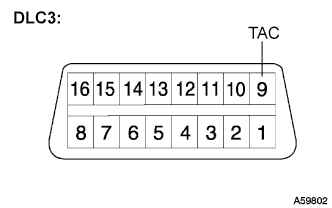
Install SST to terminal 9 (TAC) of DLC3, then connect a tachometer.
- SST
- 09843-18030
Note
Confirm the terminal numbers before connecting them. Connecting the wrong terminals can damage the engine.
-
Turn the ignition switch to the ON position.
-
Inspect the engine idling speed.
Idle speed 600 to 700 rpm -
Turn the ignition switch off.
-
Disconnect the tachometer.
-
Remove the SST from terminal 9 (TAC).
- SST
- 09843-18030
-
-
-
INSPECT CO (for Leaded Gasoline Specification Vehicle)
Tech Tips
This check is used only to determine whether or not the idle CO complies with regulations.
-
Initial condition:
-
Engine at normal operating temperature
-
Air cleaner installed
-
All pipes and hoses of the air induction system connected
-
All accessories switched off
-
All vacuum lines properly connected
-
EFI system wiring connectors fully seated
-
Ignition timing set correctly
-
Transmission in the neutral position
-
Tachometer and CO meter calibration at idle
Note
If a CO meter is not available, do not attempt to adjust the idle mixture. Always use a CO meter when adjusting the idle mixture. It is unnecessary to use the idle mixture screw for adjustments if the vehicle is in good condition.
-
-
Warm up the engine by driving at constant speed (approximately 50 km/h (31 mph)). Close the throttle valve for 5 minutes after the engine coolant temperature becomes stable (80 to 90°C (176 to 194°F)) and idle the engine for 5 minutes.
-
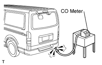
Insert a tester probe at least 40 cm (1.3 ft) into the tail pipe.
-
Wait at least 1 minute before measurement to allow the concentration to stabilize. Complete the measurement within 3 minutes.
Idle CO concentration 1.0 to 2.0% -
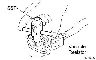
If the CO concentration does not conform to regulations, adjust it by turning the idle mixture adjusting screw in the variable resistor with SST.
- SST
- 09243-00020
-
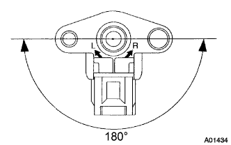
The idle mixture adjusting screw can be adjusted within an 180° angle range.
Tech Tips
-
If the CO concentration is within the specification, this adjustment is complete.
-
If the CO concentration cannot be corrected by idle mixture adjustment, see the table below for other possible causes.
-
-
Remove the SST.
CO Problems Causes High Rough idle (black smoke from exhaust)
-
Clogged air filter
-
Plugged ventilation valve
-
Faulty SFI system:
-
Faulty fuel pressure regulator
-
Clogged fuel return line
-
Defective engine coolant temperature (ECT) sensor
-
Faulty ECM
-
Faulty injectors
-
Faulty throttle position sensor
-
Faulty MAF meter
-
-
-
INSPECT CO,HC (for Unleaded Gasoline Specification Vehicle)
Tech Tips
The ECM properly controls the CO/HC concentration in the emission gas.
-
Start the engine.
-
Run the engine at 2,500 rpm for approximately 180 seconds.
-
Insert the CO/HC meter testing probe at least 40 cm (1.3 ft) into the tail pipe while idling.
-
Check the CO/HC concentration with the engine idling and/or running at 2,500 rpm.
Tech Tips
-
If the CO/HC concentration does not comply with the regulations, troubleshoot in the order given below.
-
Check the heated oxygen sensor operation Click here.
-
Check the heated air fuel ratio sensor operation Click here.
-
See the table below for possible causes, then inspect the applicable causes and repair them if necessary.
CO HC Problems Causes Normal High Rough idle
-
Faulty ignitions:
-
Incorrect timing
-
Fouled, shorted or improperly gapped plugs
-
Incorrect valve clearance
-
Leaks in intake and exhaust valves
-
Leaks in cylinders
Low High Rough idle (Fluctuating HC reading)
-
Vacuum leaks:
-
PCV hoses
-
Intake manifold
-
Throttle body
-
Brake booster line
-
Lean mixture causing misfire
High High Rough idle (Black smoke from exhaust)
-
Restricted air filter
-
Plugged PCV valve
-
Faulty SFI systems:
-
Faulty pressure regulator
-
Defective engine coolant temperature sensor
-
Defective mass air flow meter
-
Faulty ECM
-
Faulty injectors
-
Faulty throttle body
-
-
-
INSPECT FUNCTION OF THROTTLE BODY
-
Check the throttle control motor operating sounds.
-
Turn the ignition switch to the ON position.
-
When pressing the accelerator pedal, listen to the running sounds of the motor. Make sure no friction noise comes from the motor.
If friction noise exists, replace the throttle body.
-
-
Check the throttle position sensor.
-
Connect the intelligent tester to the DLC3.
-
Turn the ignition switch to the ON position.
-
Turn the intelligent tester main switch on.
-
Enter the following menus: Power train / Engine / Data List / Throttle Sensor Position and Throttle Position Sensor Position #2.
-
Depress the accelerator pedal. When the throttle valve is fully opened, check that the value of the "Throttle Sensor Position" is within the specification.
Standard throttle valve opening percentage 60% or more Note
When checking the standard throttle valve opening percentage, the shift lever should be in the N position.
Tech Tips
If the percentage is less than 60%, replace the throttle body.
-
-
-
INSPECT ABS SENSOR SIGNAL (w/ ABS)
-
PERFORM INITIALIZATION