CYLINDER HEAD REMOVAL

-
REMOVE MANUAL TRANSMISSION UNIT ASSEMBLY (for Manual Transmission)
-
REMOVE AUTOMATIC TRANSMISSION ASSEMBLY (for Automatic Transmission)
-
REMOVE CHAIN SUB-ASSEMBLY
-
REMOVE CAMSHAFT BEARING CAP
-
Uniformly loosen and remove the 21 bearing cap bolts and 20 washers on the camshafts in the sequence shown in the illustration.
-
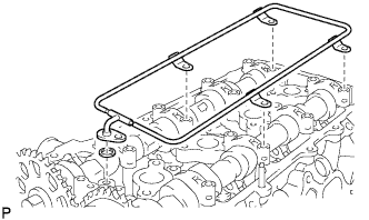
Remove the oil delivery pipe and O-ring from the bearing caps.
-
Remove the 9 bearing caps.
-
-
REMOVE CAMSHAFT
-
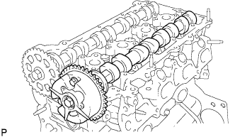
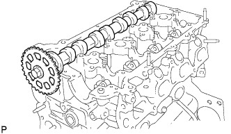
Remove the camshaft sub-assembly.
-
-
REMOVE NO.2 CAMSHAFT
-
Remove the No.2 camshaft sub-assembly.
-
-
REMOVE VALVE ROCKER ARM SUB-ASSEMBLY NO.1
Tech Tips
Make sure that the removed parts are returned to the same places they were removed from.
-
REMOVE VALVE LASH ADJUSTER ASSEMBLY
Tech Tips
Make sure that the removed parts are returned to the same places they were removed from.
-
REMOVE VALVE STEM CAP
Tech Tips
Make sure that the removed parts are returned to the same places they were removed from.
-
INSPECT VALVE LASH ADJUSTER ASSEMBLY
Note
-
Keep the lash adjuster free from dirt and foreign objects.
-
Use only clean engine oil.
-
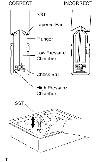
Place the lash adjuster into a container full of engine oil.
-
Insert the tip of SST into the lash adjuster's plunger and use the tip to press down on the checkball inside the plunger.
- SST
- 09276-75010
-
Squeeze the SST and lash adjuster together to move the plunger up and down 5 to 6 times.
-
Check the movement of the plunger and bleed air.
OK Plunger moves up and down. Note
When bleeding high-pressure air from the compression chamber, make sure that the tip of the SST is actually pressing the checkball as shown in the illustration. If the checkball is not pressed, air will not bleed.
-
After bleeding air, remove the SST. Then quickly and firmly press the plunger with a finger.
OK Plunger is very difficult to move. If the result is not as specified, replace the lash adjuster.
-
-
INSPECT CAMSHAFT TIMING GEAR ASSEMBLY
-
Check the lock of the camshaft timing gear.
-
Clamp the camshaft in a vise, and confirm that the camshaft timing gear is locked.
Note
Be careful not to damage the camshaft.
-
-
Release the lock pin.
-
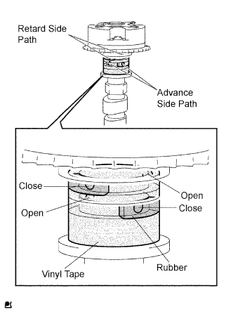
Cover the 4 oil paths of the cam journal with vinyl tape as shown in the illustration.
Tech Tips
2 advance side paths are provided in the groove of the camshaft. Plug one of the paths with a rubber piece.
-
Break through the tape of the advance side path and the retard side path on the opposite side to the hole of the advance side path.
-
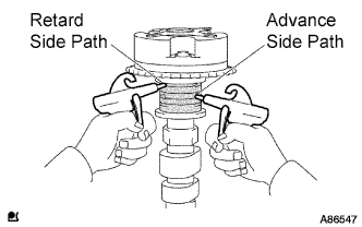
Apply approximately 200 kPa (2.0 kgf/cm2, 28 psi) of air pressure to the two broken paths.
Note
Some oil splashing will occur. Cover the paths with a shop rag or a piece of cloth.
-
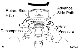
Check that the camshaft timing gear revolves in the advance direction when reducing the air pressure applied to the retard side path.
OK Gear rotates in the advance direction. Tech Tips
This operation releases the lock pin for the most retarded position.
-
When the camshaft timing gear reaches the most advanced position, release the air pressure from the retard side path and advance side path, in that order.
Note
Do not release the air pressure from the advance side path first. The gear may abruptly shift in the retard direction and break the lock pin.
-
-
Check for smooth rotation.
-
Rotate the camshaft timing gear within its movable range several times, but do not turn it to the most retarded position. Check that the gear rotates smoothly.
OK Gear rotates in the advance direction. Note
Do not use air pressure to perform the smooth operation check.
-
-
Check the lock in the most retarded position.
-
Confirm that the camshaft timing gear is locked at the most retarded position.
-
-
-
REMOVE CYLINDER HEAD SUB-ASSEMBLY
-
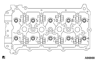
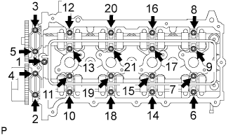
Uniformly loosen the 10 bolts in the sequence shown in the illustration. Remove the 10 cylinder head bolts and plate washers.
Note
-
Be careful not to drop washers into the cylinder head.
-
Head warpage or cracking could result from removing bolts in incorrect order.
-
-
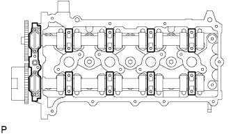
Remove the cylinder head sub-assembly.
-
-
REMOVE CYLINDER HEAD GASKET