CAMSHAFT INSTALLATION

-
INSTALL CAMSHAFT TIMING GEAR ASSEMBLY
-
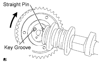
Put the camshaft timing gear and camshaft together by aligning the key groove and straight pin.
-
Lightly press the gear against the camshaft, and turn the gear. Push further at the position where the pin enters the groove.
Note
Be sure not to turn the camshaft timing gear in the retard direction (the right angle).
-
Check that there is no clearance between the gear's flange and the camshaft.
Note
-
Since the thrust clearance of the camshaft is small, the camshaft must be kept level while it is being removed. If the camshaft is not kept level, the portion of the cylinder head receiving the shaft thrust may crack or be damaged, causing the camshaft to seize or break.
-
Be sure not to remove the other 3 bolts. If removing the bolts, exchange the camshaft timing gear assembly.
-
-
Tighten the flange bolt with the camshaft timing gear fixed.
- Torque:
- 78 N*m { 795 kgf*cm, 59 ft.*lbf }
-
Check that the camshaft timing gear assembly can move in the retard direction (the right angle), and is locked at the most retarded position.
-
-
INSTALL CAMSHAFT
-
Apply clean engine oil to the camshaft's cam portion and the cylinder head journals.
-
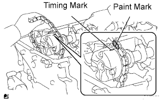
Install the timing chain on the camshaft timing gear, with the painted mark of the link aligned with the timing mark of the camshaft timing gear.
Note
Align the paint mark and timing mark before setting the camshaft.
-
-
INSTALL NO.2 CAMSHAFT
-
Apply clean engine oil to the camshaft's cam portion and the cylinder head journals.
-
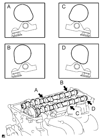
Install the No.2 camshaft on the cylinder head.
Tech Tips
Set the 2 camshaft's as shown in the illustration.
-
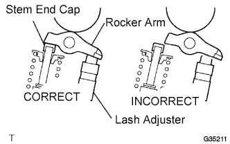
Before and after setting the camshaft and No.2 camshaft, check that the rocker arm is firmly set to the lash adjuster.
-
-
INSTALL CAMSHAFT BEARING CAP
-
Temporarily install the camshaft bearing cap No.1.
-
Check the proper location of each camshaft bearing cap and install them.
-
Install a new O-ring to the camshaft bearing cap No.1.
-
Temporarily install the oil delivery pipe.
-
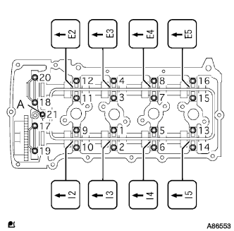
Tighten the bolts in the order shown in the illustration.
- Torque:
- Bolt A
- 12 N*m { 122 kgf*cm, 9 ft.*lbf }
- Except bolt A
- 16 N*m { 160 kgf*cm, 11 ft.*lbf }
Note
Uniformly tighten the bolts holding the camshaft horizontaly.
-
-
INSTALL CAMSHAFT TIMING GEAR OR SPROCKET
-
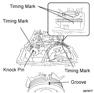
Rotate the camshaft so that the camshaft's timing mark and the camshaft No.2 knock pin are positioned as shown in the illustration.
-
Turn the crankshaft pulley, and align its groove with timing mark 0 of the timing chain cover.
-
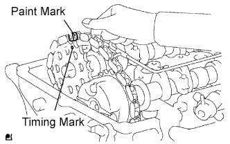
Install the timing chain on the camshaft timing sprocket, with the paint mark aligned with the timing marks on the camshaft timing sprocket.
-
Align the camshaft No.2 knock pin and the camshaft timing sprocket's pin hole. Then install the camshaft timing sprocket to the camshaft No.2.
Note
If the knock pin and pin hole are difficult to align, slightly rotate the camshaft No.2 to the left and right using the camshaft's hexagon-shaped part. Then attempt alignment again.
-
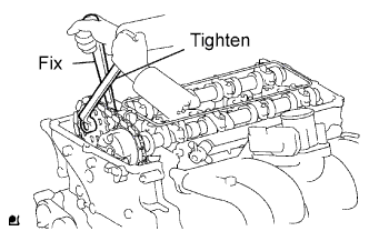
Fix the camshaft with a wrench, and then tighten the sprocket bolt.
- Torque:
- 78 N*m { 795 kgf*cm, 58 ft.*lbf }
-
Remove the hexagon wrench from the chain tensioner.
-
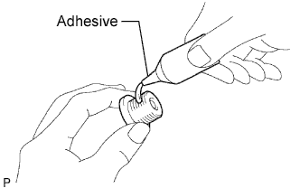
Apply adhesive to 2 or 3 threads of the timing chain cover plug.
Adhesive Toyota Genuine Adhesive 1324, Three Bond 1324 or equivalent Note
Remove any oil from the bolt hole.
-
Using a 10 mm socket hexagon wrench, install the timing gear case plug.
- Torque:
- 17 N*m { 170 kgf*cm, 13 ft.*lbf }
-
-
INSTALL TIMING CHAIN GUIDE
-
Install a new O-ring to the camshaft bearing cap.
-
Install the timing chain guide with the 2 bolts.
- Torque:
- 10 N*m { 102 kgf*cm, 7 ft.*lbf }
-
-
INSTALL CYLINDER HEAD COVER SUB-ASSEMBLY
-
Remove any old packing (FIPG) material.
-
Install the cylinder head cover gasket and cylinder head gasket No.2 to the cylinder head cover.
-
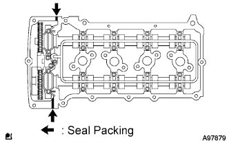
Apply seal packing to 2 locations as shown in the illustration.
Seal packing Toyota Genuine Seal Packing Black, Three Bond 1207B or equivalent Note
-
Remove any oil from the contact surface.
-
Install the cylinder head cover within 3 minutes after applying seal packing.
-
Do not start the engine for at least 4 hours after installing.
-
-
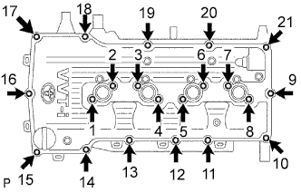
Temporarily install the head cover with the 19 bolts and 2 nuts.
-
Uniformly tighten the 19 bolts and 2 nuts in the sequence shown in the illustration.
- Torque:
- 9.0 N*m { 92 kgf*cm, 80 in.*lbf }
-
After tightening the 19 bolts and 2 nuts at the specified torque, retighten 1-8 bolts at the torque.
-
Connect the wire harness to the 6 clamps.
-
Connect the ventilation hose No.1.
-
-
INSTALL IGNITION COIL ASSEMBLY
-
Install the ignition coils with the bolts.
- Torque:
- 9.0 N*m { 92 kgf*cm, 80 in.*lbf }
-
-
INSTALL INTAKE AIR CONNECTOR
-
Temporarily install the intake air connector to the throttle body assembly.
-
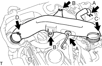
Connect the ventilation hose No.2 and the vacuum hose. (A)
-
Install the intake air connector with the 2 bolts. (B)
- Torque:
- 8.0 N*m { 82 kgf*cm, 71 in.*lbf }
-
Tighten the 2 hose clamp bolts. (C)
- Torque:
- 5.0 N*m { 51 kgf*cm, 44 in.*lbf }
-
Tighten the 2 hose clamp bolts. (D)
-
-
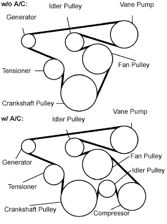
INSTALL FAN & GENERATOR V BELT
-
Install the drive belt to the pulleys except the drive belt tensioner pulley.
-
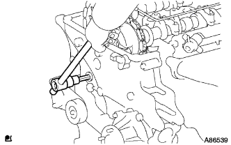
Use the hexagon-shaped part indicated by the arrow in the illustration to move the tensioner pulley downward and then install the drive belt to the tensioner pulley.
Note
-
The backside of the drive belt should face the tensioner pulley.
-
Check that the drive belt is properly set to each pulley.
-
-
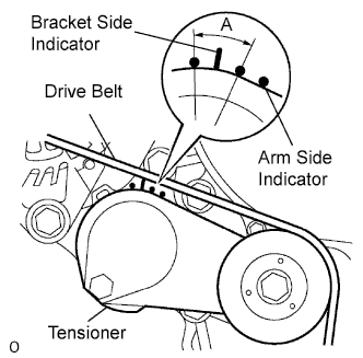
After a new belt has been installed, check that the tensioner indicator mark is within range A shown in the illustration.
-
-
INSTALL ENGINE SERVICE HOLE SUB COVER SUB-ASSEMBLY
-
Install the engine service hole sub cover with the 5 bolts.
- Torque:
- 13 N*m { 133 kgf*cm, 10 ft.*lbf }
-
-
INSTALL FRONT DOOR SCUFF PLATE RH
-
INSTALL FRONT SEAT ASSEMBLY RH (for Hi-back Seat Type)
-
Perform the same procedure as above on the opposite side. Click here
-
-
INSTALL FRONT SEAT ASSEMBLY RH (for Low-back Seat Type)
-
Perform the same procedure as above on the opposite side. Click here
-
-
INSPECT ENGINE OIL LEAKS
-
INSTALL ENGINE UNDER COVER NO.1 (w/ Engine Under Cover No.1)
- Torque:
- 13 N*m { 133 kgf*cm, 10 ft.*lbf }