CAMSHAFT REMOVAL

-
REMOVE ENGINE UNDER COVER NO.1 (w/ Engine Under Cover No.1)
-
REMOVE FRONT SEAT ASSEMBLY RH (for Hi-back Seat Type)
-
Perform the same procedure as above on the opposite side. Click here
-
-
REMOVE FRONT SEAT ASSEMBLY RH (for Low-back Seat Type)
-
Perform the same procedure as above on the opposite side. Click here
-
-
REMOVE FRONT DOOR SCUFF PLATE RH
-
REMOVE ENGINE SERVICE HOLE SUB COVER SUB-ASSEMBLY
-
Roll up the carpet, and remove the 5 bolts and engine service hole sub cover.
-
-
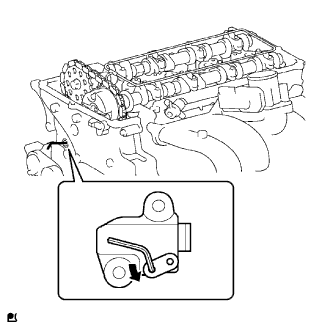
REMOVE FAN & GENERATOR V BELT
-
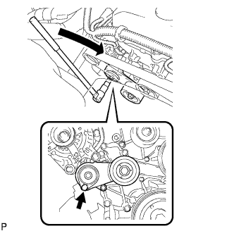
Use the hexagon-shaped part indicated by the arrow in the illustration to move the tensioner pulley downward and decrease the tension in the drive belt. Then remove the drive belt.
Note
When removing the drive belt, do not use the idle pulley's bolt.
Tech Tips
After removing the drive belt, move the tensioner upward to the maximum amount.
-
-
REMOVE AIR PRESSURE SENSOR (w/ Manifold Absolute Pressure Sensor)
-
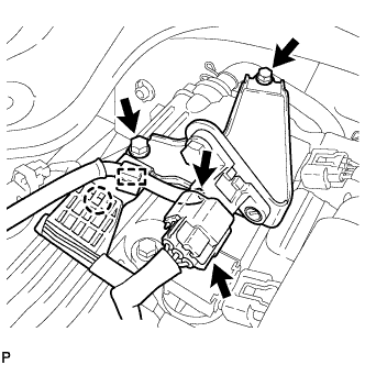
Disconnect the connector.
-
Disconnect the vacuum hose and clamp.
-
Detach the wire harness clamp
-
Remove the 2 bolts and air pressure sensor together with the bracket.
-
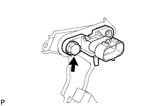
Remove the bolt and air pressure sensor.
-
-
REMOVE INTAKE AIR CONNECTOR
-
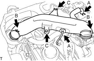
Disconnect the ventilation hose No.2 and the vacuum hose.(A)
-
Loosen the 2 hose clamp bolts.(B)
-
Remove the 2 bolts, then remove the intake air connector.(C)
-
-
REMOVE IGNITION COIL ASSEMBLY
-
Remove the bolts and ignition coil assembly.
-
-
REMOVE CYLINDER HEAD COVER SUB-ASSEMBLY
-
Disconnect the ventilation hose No.1.
-
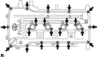
Remove the 19 bolts, 2 nuts, head cover and 2 gaskets.
-
Remove the cylinder head cover gasket and cylinder head cover gasket No.2 from the cylinder head cover.
-
-
REMOVE TIMING CHAIN GUIDE
-
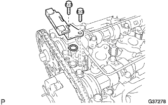
Remove the 2 bolts, timing chain guide and O-ring.
-
-
REMOVE CAMSHAFT TIMING GEAR OR SPROCKET
-
Set No.1 cylinder to TDC/compression.
-
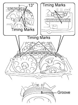
Turn the crankshaft pulley, and align its groove with timing mark 0 of the timing chain cover.
-
Check that the timing marks of the camshaft timing gear and sprocket are aligned with the timing marks of bearing cap No.1, as shown in the illustration.
Tech Tips
If not, turn the crankshaft pulley 1 revolution (360°) and align the marks as above.
-
-
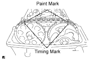
Put paint marks on the timing chain and camshaft timing gear/sprocket.
-
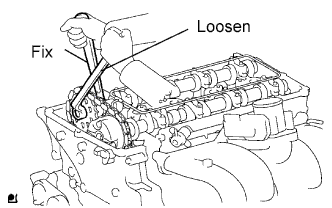
Fix the camshaft with a wrench and then loosen the sprocket bolt.
Note
Be careful not to damage the oil delivery pipe.
-
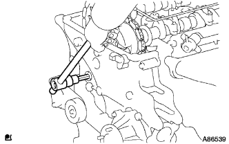
Using a 10 mm socket hexagon wrench, remove the timing chain cover plug.
-
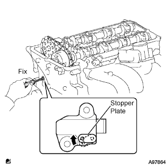
Using a screwdriver, access the tensioner stopper plate through the chain tensioner service hole. Move the stopper plate upward to release the lock. Then hold the plate in that position as shown in the illustration.
Tech Tips
If the stopper plate's lock is difficult to release, slightly rotate the camshaft's hexagon-shaped part to the left and right.
-
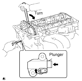
With the stopper plate's lock released, slightly rotate the camshaft to the right. Then maintain it in that position.
Note
Be careful not to damage the oil delivery pipe.
Tech Tips
Rotating the camshaft to the right will cause pressure to be applied to the tensioner plunger.
-
Remove the screwdriver from the chain tensioner service hole. Move the stopper plate to the position shown in the illustration. Then insert a hexagon wrench into the hole.
Tech Tips
-
If the wrench cannot fit into the hole, slightly rotate the camshaft to the left and then to the right. Then insert the wrench.
-
To prevent the wrench from falling out, use tape to fix the wrench in place.
-
-
Remove the camshaft timing sprocket from the camshaft.
-
-
REMOVE CAMSHAFT BEARING CAP
-
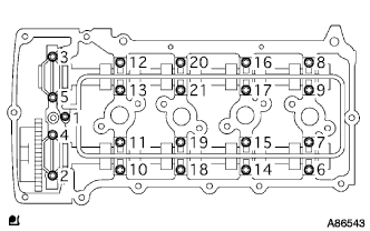
Uniformly loosen the 21 bearing cap bolts in several steps in the sequence shown in the illustration.
-
Remove the 9 bearing caps, oil delivery pipe, O-ring and camshaft.
Note
-
Place the camshaft on a flat surface and loosen the bolts uniformly.
-
Do not pry the camshaft with a tool by applying excessive force to it.
-
Do not damage the reception part of the camshaft on the cylinder head side.
-
-
-
REMOVE NO.2 CAMSHAFT
-
REMOVE CAMSHAFT
-
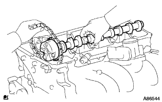
Remove the camshaft while holding the timing chain.
-
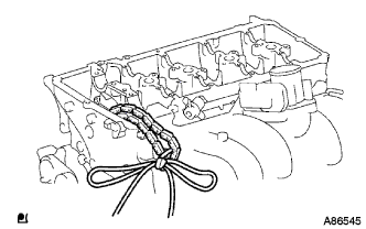
Tie the timing chain with a string as shown in the illustration.
Note
Be careful not to drop anything inside the timing chain cover.
-
-
INSPECT CAMSHAFT TIMING GEAR ASSEMBLY
-
Check the lock of the camshaft timing gear.
-
Clamp the camshaft in a vise, and confirm that the camshaft timing gear is locked.
Note
Be careful not to damage the camshaft.
-
-
Release the lock pin.
-
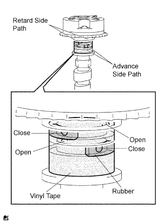
Cover the 4 oil paths of the cam journal with vinyl tape as shown in the illustration.
Tech Tips
2 advance side paths are provided in the groove of the camshaft. Plug one of the paths with a rubber piece.
-
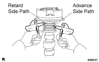
Break through the tape of the advance side path and the retard side path on the opposite side to the hole of the advance side path.
-
Apply approximately 200 kPa (2.0 kgf/cm2, 28 psi) of air pressure to the two broken paths.
Note
Some oil splashing will occur. Cover the paths with a shop rag or a piece of cloth.
-
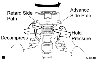
Check that the camshaft timing gear revolves in the advance direction when reducing the air pressure applied to the retard side path.
OK Gear rotates in the advance direction. Tech Tips
This operation releases the lock pin for the most retarded position.
-
When the camshaft timing gear reaches the most advanced position, release the air pressure from the retard side path and advance side path, in that order.
Note
Do not release the air pressure from the advance side path first. The gear may abruptly shift in the retard direction and break the lock pin.
-
-
Check for smooth rotation.
-
Rotate the camshaft timing gear within its movable range several times, but do not turn it to the most retarded position. Check that the gear rotates smoothly.
OK Gear rotates in the advance direction. Note
Do not use air pressure to perform the smooth operation check.
-
-
Check the lock in the most retarded position.
-
Confirm that the camshaft timing gear is locked at the most retarded position.
-
-
-
REMOVE CAMSHAFT TIMING GEAR ASSEMBLY
-
Check that the camshaft timing gear assembly does not turn by mounting the hexagon wrench head portion of the camshaft in a vise through aluminium metal cap and so on.
Note
Be sure not to damage the camshaft.
-
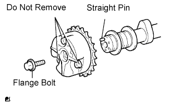
Remove the flange bolt and camshaft timing gear.
Note
-
Be sure not to remove the other 3 bolts.
-
If planning to reuse the gear, be sure to release the straight pin lock before installing the gear.
-
-