DRIVE BELT INSTALLATION

-
INSTALL TENSIONER PULLEY
Note
Perform the following procedure when it is necessary to replace the tensioner pulley.
Tech Tips
The tensioner pulley service kit consists of a bolt, nut, dust seal and tensioner pulley.
-
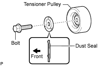
Install the dust seal and bolt to the tensioner pulley as shown in the illustration.
Note
-
The dust seal must be oriented correctly when installed. If the dust seal is installed incorrectly, the bearing may be damaged.
-
Do not touch the seal surface of the bearing.
Tech Tips
Be sure to use the bolt and nut from the service kit.
-
-
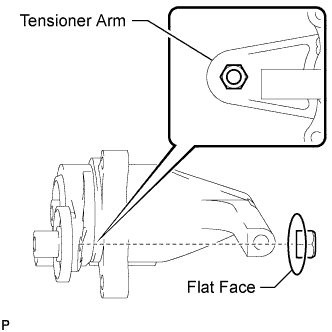
Set the nut in place on the tensioner arm so that the flat face of the nut contacts the tensioner arm as shown in the illustration.
Note
Make sure the nut is not installed backwards.
-
Tighten the bolt by hand until the flange of the bolt contacts the dust seal and the tensioner pulley is fixed in place.
Note
-
Perform this procedure while holding the nut in place on the tensioner arm so that it does not fall.
-
Do not use any tools.
-
-
Tighten the bolt.
- Torque:
- 47 N*m { 479 kgf*cm, 35 ft.*lbf }
-
-
INSTALL FAN & GENERATOR V BELT
-
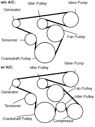
Install the drive belt to the pulleys except the drive belt tensioner pulley.
-
Use the hexagon-shaped part indicated by the arrow in the illustration to move the tensioner pulley downward and then install the drive belt to the tensioner pulley.
Note
-
The backside of the drive belt should face the tensioner pulley.
-
Check that the drive belt is properly set to each pulley.
-
-
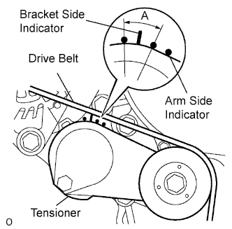
After a new belt has been installed, check that the tensioner indicator mark is within range A shown in the illustration.
-
-
INSTALL ENGINE SERVICE HOLE SUB COVER SUB-ASSEMBLY
-
Install the engine service hole cover with the 5 bolts.
- Torque:
- 13 N*m { 133 kgf*cm, 10 ft.*lbf }
-
-
INSTALL FRONT DOOR SCUFF PLATE RH
-
INSTALL FRONT SEAT ASSEMBLY RH (for Hi-back Seat Type)
-
Perform the same procedure as above on the opposite side. Click here
-
-
REMOVE FRONT SEAT ASSEMBLY RH (for Low-back Seat Type)
-
Perform the same procedure as above on the opposite side. Click here
-