ENGINE UNIT DISASSEMBLY

-
REMOVE OIL FILLER CAP SUB-ASSEMBLY
-
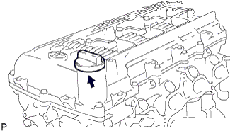
Remove the oil filler cap sub-assembly.
-
-
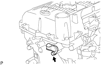
REMOVE VENTILATION VALVE SUB-ASSEMBLY
-
Remove the ventilation valve sub-assembly.
-
-
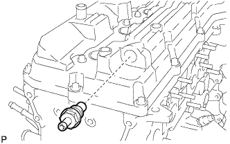
REMOVE CAM POSITION SENSOR
-
Remove the bolt and camshaft position sensor.
-
-
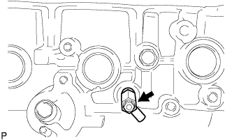
REMOVE CRANK POSITION SENSOR
-
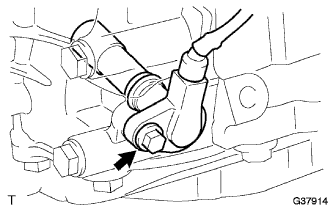
Remove the bolt and crank position sensor.
-
-
REMOVE CAMSHAFT TIMING OIL CONTROL VALVE ASSEMBLY
-
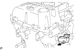
Remove the bolt and camshaft timing oil control valve.
-
-
REMOVE CYLINDER HEAD COVER SUB-ASSEMBLY
-
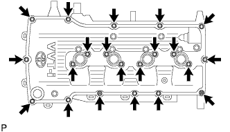
Remove the 19 bolts, 2 nuts, head cover and 2 gaskets.
-
-
REMOVE CRANKSHAFT PULLEY
-
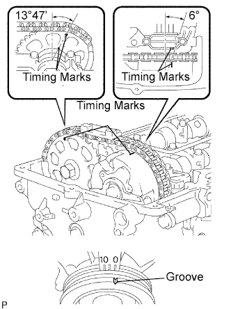
Turn the crankshaft pulley, and align its groove with timing mark 0 of the timing chain cover.
-
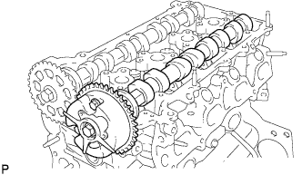
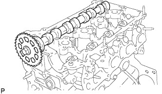
Check that the timing marks of the camshaft timing gear and sprocket are aligned with the timing marks of the bearing cap No.1, as shown in the illustration.
-
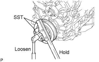
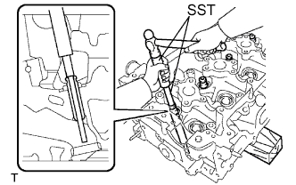
Using SST, loosen the crankshaft pulley bolt.
- SST
- 09213-54015 ( 91651-60855 )
- 09330-00021
-
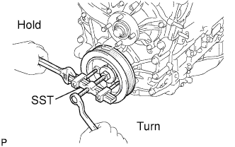
Using SST, remove the crankshaft pulley bolt and crankshaft pulley.
- SST
- 09950-50013 ( 09951-05010, 09952-05010, 09953-05010, 09954-05021 )
-
-
REMOVE OIL PAN SUB-ASSEMBLY NO.2
-
Remove the drain plug and gasket.
-
Remove the 18 bolts and 2 nuts.
-
Insert the blade of an oil pan seal cutter between the oil pans. Cut through the applied sealer and remove the oil pan sub-assembly No.2.
Note
Do not damage the contact surfaces of the oil pans.
-
-
REMOVE OIL STRAINER SUB-ASSEMBLY
-
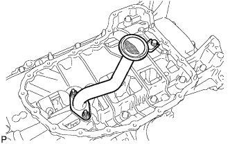
Remove the bolt, 2 nuts, oil strainer and gasket.
-
-
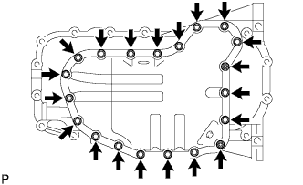
REMOVE OIL PAN SUB-ASSEMBLY
-
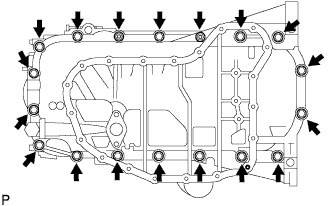
Remove the 16 bolts and 2 nuts.
-
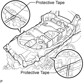
Remove the oil pan by prying between the oil pan and cylinder block with a screwdriver.
Note
Do not damage the contact surfaces of the cylinder block and oil pan.
Tech Tips
Tape the screwdriver tip before use.
-
Remove the O-ring.
-
-
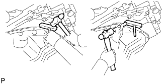
REMOVE TIMING CHAIN OR BELT COVER SUB-ASSEMBLY
-
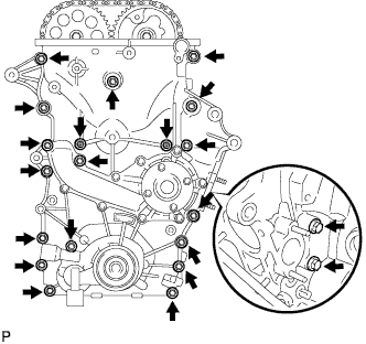
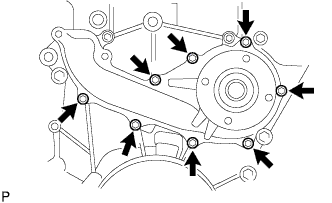
Remove the 19 bolts and 2 nuts shown in the illustration (w/o air conditioning).
-
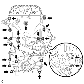
Remove the 17 bolts and 2 nuts shown in the illustration (w/ air conditioning).
-
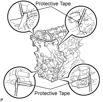
Remove the timing chain cover by prying between the timing chain cover and cylinder head or cylinder block with a screwdriver.
Tech Tips
Tape the screwdriver tip before use.
Note
Do not damage the contact surfaces of the cylinder head, cylinder block and timing chain cover.
-
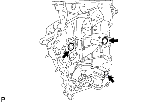
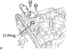
Remove the 3 O-rings.
-
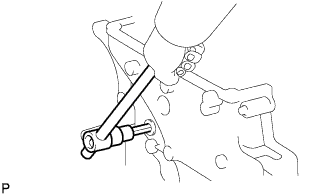
Using a 10 mm socket hexagon wrench, remove the timing chain cover plug.
-
-
REMOVE WATER PUMP ASSEMBLY
-
Remove the 8 bolts, water pump and gasket.
-
-
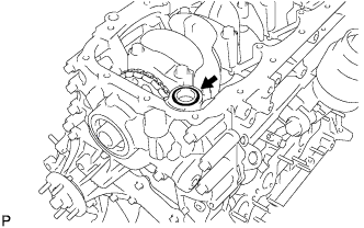
REMOVE TIMING CHAIN CASE OIL SEAL
-
Using a screwdriver with its tip taped, pry out the oil seal.
Tech Tips
Tape the screwdriver tip before use.
-
-
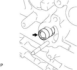
REMOVE OIL PUMP RELIEF VALVE
-
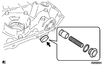
Using a 27 mm socket wrench, remove the plug and gasket.
-
Remove the valve spring and relief valve.
-
-
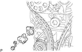
REMOVE TIMING CHAIN GUIDE
-
Remove the 2 bolts, timing chain guide and O-ring.
-
-
REMOVE CHAIN TENSIONER ASSEMBLY NO.1
Note
-
When the chain tensioner is removed, do not rotate the crankshaft.
-
When the chain is removed and the camshaft needs to be rotated, rotate the crankshaft 90 degrees to the right.
-
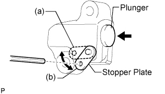
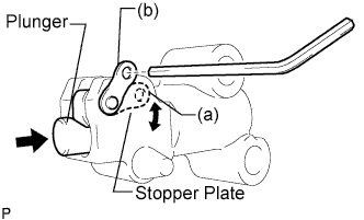
Move the stopper plate upward to release the lock, and push the plunger deep into the tensioner.
-
Move the stopper plate downward to set the lock, and insert a hexagon wrench into the stopper plate hole.
-
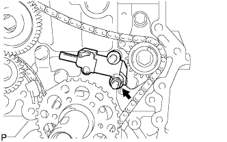
Remove the bolt, nut, chain tensioner assembly No.1 and gasket.
-
-
REMOVE CHAIN TENSIONER SLIPPER
-
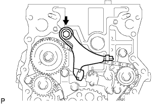
Remove the bolt and tensioner slipper.
-
-
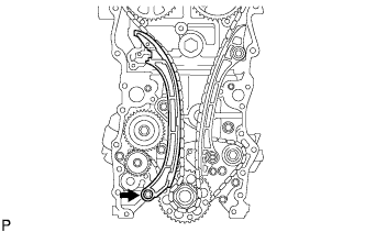
REMOVE CHAIN VIBRATION DAMPER NO.1
-
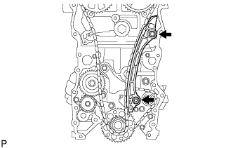
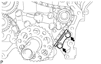
Remove the bolt, nut, and vibration damper.
-
-
REMOVE CHAIN SUB-ASSEMBLY
-
Remove the chain.
-
-
REMOVE CRANKSHAFT TIMING GEAR OR SPROCKET
-
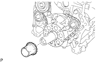
Remove the crankshaft timing gear from the crankshaft.
-
-
REMOVE CAMSHAFT BEARING CAP
-
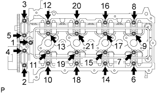
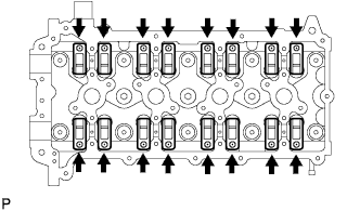
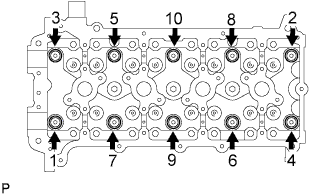
Uniformly loosen and remove the 21 bearing cap bolts and 20 washers on the camshafts in the sequence shown in the illustration.
-
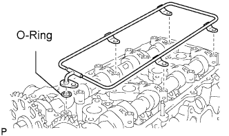
Remove the oil delivery pipe and O-ring from the bearing caps.
-
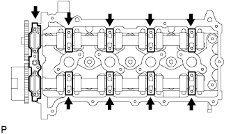
Remove the 9 bearing caps.
-
-
REMOVE CAMSHAFT
-
Remove the camshaft sub-assembly.
-
-
REMOVE NO.2 CAMSHAFT
-
Remove the No.2 camshaft sub-assembly.
-
-
REMOVE VALVE ROCKER ARM SUB-ASSEMBLY NO.1
-
Remove the 16 valve rocker arm sub-assemblies.
-
-
REMOVE CAMSHAFT TIMING GEAR OR SPROCKET
-
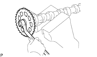
Fix the camshaft with a vise and then remove the sprocket bolt and camshaft timing sprocket.
Note
Do not damage the camshaft.
-
-
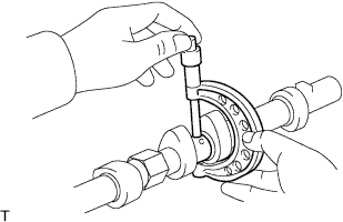
INSPECT CAMSHAFT TIMING GEAR ASSEMBLY
-
Check the lock of the camshaft timing gear.
-
Clamp the camshaft in a vise, and confirm that the camshaft timing gear is locked.
Note
Do not damage the camshaft.
-
-
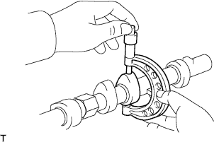
Release the lock pin.
-
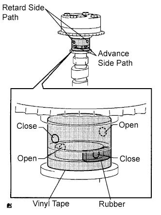
Cover the 4 oil paths of the cam journal with vinyl tape as shown in the illustration.
Tech Tips
2 advance side paths are provided in the groove of the camshaft. Plug one of the paths with a rubber piece.
-
Break through the tape of the advance side path and the retard side path on the opposite side to the hole of the advance side path, as shown in the illustration.
-
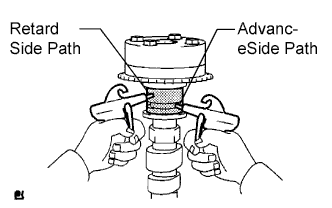
Apply approximately 200 kPa (2.0 kgf/cm2, 28 psi) of air pressure to the two broken paths.
CAUTION:
Some oil splashing will occur. Cover the paths with a shop rag or piece of cloth.
-
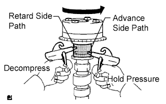
Check that the camshaft timing gear revolves in the advance direction when reducing the air pressure applied to the retard side path.
OK Gear rotates in the advance direction. Tech Tips
This operation releases the lock pin for the most retarded position.
-
When the camshaft timing gear reaches the most advanced position, release the air pressure from the retard side path and advance side path, in that order.
Note
Do not release the air pressure from the advance side path first. The gear may abruptly shift in the retard direction and break the lock pin.
-
-
Check for smooth rotation.
-
Rotate the camshaft timing gear within its movable range several times, but do not turn it to the most retarded position. Check that the gear rotates smoothly.
OK Gear rotates in the advance direction. CAUTION:
Do not use air pressure to perform the smooth operation check.
-
-
Check the lock in the most retarded position.
-
Confirm that the camshaft timing gear is locked at the most retarded position.
-
-
-
REMOVE CAMSHAFT TIMING GEAR ASSEMBLY
-
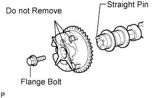
Remove the fringe bolt and camshaft timing gear.
Note
-
Do not remove the other 3 bolts.
-
If planning to reuse the gear, be sure to release the straight pin lock before installing the gear.
-
-
-
REMOVE CYLINDER HEAD SUB-ASSEMBLY
-
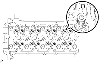
Uniformly loosen the 10 bolts in the sequence shown in the illustration. Remove the 10 cylinder head bolts and plate washers.
Note
-
Do not drop washers into the cylinder head.
-
Head warpage or cracking could result from removing bolts in an incorrect order.
-
-
Remove the cylinder head.
-
-
REMOVE CYLINDER HEAD GASKET
-
Remove the cylinder head and gasket.
-
-
REMOVE CHAIN VIBRATION DAMPER NO.2
-
Move the stopper plate downward to release the lock, and push the plunger deep into the tensioner.
-
Move the stopper plate upward to set the lock, and insert a hexagon wrench into the stopper plate hole.
-
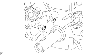
Remove the bolt and chain vibration damper No.2.
-
-
REMOVE CHAIN VIBRATION DAMPER NO.3
-
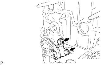
Remove the 2 bolts and chain vibration damper No.3.
-
-
REMOVE CHAIN TENSIONER ASSEMBLY NO.2
-
Remove the hexagon wrench from the tensioner assembly
-
Remove the nut and chain tensioner assembly No.2.
-
-
REMOVE NO.2 CHAIN SUB-ASSEMBLY
-
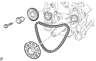
Remove the bolt, balanceshaft drive gear shaft and balanceshaft drive gear.
-
Remove the crankshaft timing sprocket No.2 and chain.
-
-
REMOVE CHAIN VIBRATION DAMPER NO.4
-
Remove the 2 bolts and vibration damper No.4.
-
-
REMOVE CRANKSHAFT PULLEY SET KEY
-
Remove the 2 pulley set keys from the crankshaft.
-
-
REMOVE OIL FILTER SUB-ASSEMBLY
-
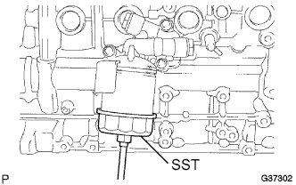
Using SST, remove the oil filter.
- SST
- 09228-06501
-
Using a 27 mm socket wrench, remove the oil filter union.
-
-
REMOVE OIL FILTER BRACKET SUB-ASSEMBLY
-
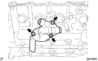
Remove the 2 bolts and nut from the oil filter bracket.
-
Remove the 2 screw plugs and 2 gaskets from the oil filter bracket.
-
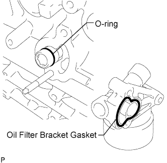
Remove the oil filter bracket gasket and O-ring.
-
Using a hexagon wrench, remove the oil filter bracket union.
-
-
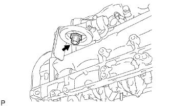
REMOVE W/HEAD TAPER SCREW PLUG NO.1
-
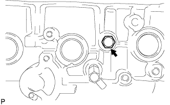
Remove the taper screw plug from the cylinder block.
-
-
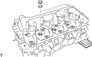
REMOVE ENGINE REAR OIL SEAL RETAINER
-
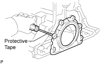
Remove the 6 bolts.
-
Using a screwdriver with its tip taped, pry out the oil seal retainer.
Tech Tips
Tape the screwdriver tip before use.
-
-
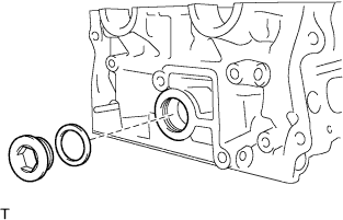
REMOVE ENGINE REAR OIL SEAL
-
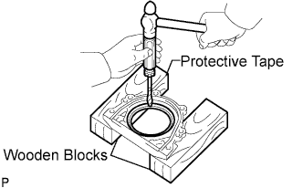
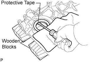
Place the oil seal retainer on wooden blocks.
-
Using a screwdriver with its tip taped and a hammer, tap out the oil seal.
Tech Tips
Tape the screwdriver tip before use.
-
-
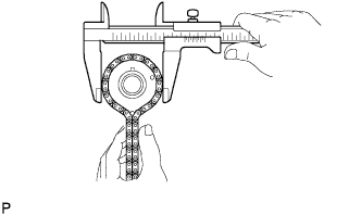
INSPECT CHAIN SUB-ASSEMBLY
-
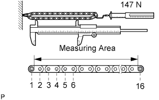
Pull the chain with a force of 147 N (15 kgf, 33 Ibf) as shown in the illustration.
-
Using vernier calipers, measure the length of 16 links.
Maximum chain elongation 147.5 mm (5.807 in.) If the elongation is greater than the maximum, replace the chain.
Note
Perform the same measurement by pulling at random in 3 or more places to obtain an average.
-
-
INSPECT NO.2 CHAIN SUB-ASSEMBLY
-
Pull the chain with a force of 147 N (15 kgf, 33 Ibf) as shown in the illustration.
-
Using vernier calipers, measure the length of 16 links.
Maximum chain elongation 123.6 mm (4.866 in.) If the elongation is greater than the maximum, replace the chain.
Note
Perform the same measurement by pulling at random in 3 or more places to obtain an average.
-
-
INSPECT CHAIN TENSIONER ASSEMBLY NO.1
-
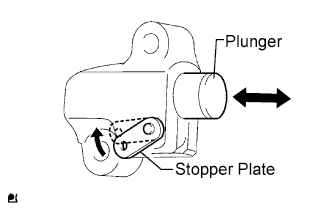
Move the stopper plate upward to release the lock. Push the plunger and check that it moves smoothly.
-
-
INSPECT CHAIN TENSIONER ASSEMBLY NO.2
-
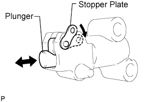
Move the stopper plate downward to release the lock. Push the plunger and check that it moves smoothly.
-
-
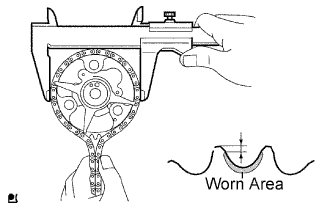
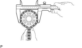
INSPECT CAMSHAFT TIMING GEAR OR SPROCKET
-
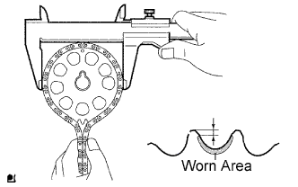
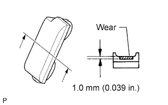
Measure the distance between the most worn out sprocket tip and the beginning of the worn area below the tip.
Minimum distance 1.0 mm (0.039 in.) If the distance is less than the minimum, replace the sprocket.
If the worn area is too small or difficult to distinguish from a normal area, perform steps (b) and (c) below.
-
Wrap the chain around the sprocket.
-
Using vernier calipers, measure the sprocket diameter with the chain.
Minimum sprocket diameter (w/ chain) 113.8 mm (4.480 in.) Tech Tips
The vernier calipers must contact the chain rollers for the measurement.
If the diameter is less than the minimum, replace the chain and sprocket.
-
-
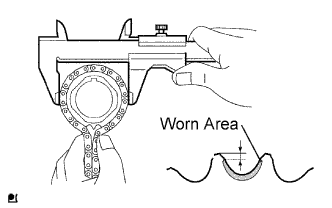
INSPECT CAMSHAFT TIMING GEAR ASSEMBLY
-
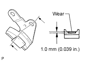
Measure the distance between the most worn out timing gear tip and the beginning of the worn area below the tip.
Minimum distance 1.0 mm (0.039 in.) If the distance is less than the minimum, replace the timing gear.
If the worn area is too small or difficult to distinguish from a normal area, perform steps (b) and (c) below.
-
Wrap the chain around the timing gear.
-
Using vernier calipers, measure the sprocket diameter with the chain.
Minimum sprocket diameter (w/ chain) 113.8 mm (4.480 in.) Tech Tips
The vernier calipers must contact the chain rollers for the measurement.
If the diameter is less than the minimum, replace the chain and timing gear.
-
-
INSPECT CRANKSHAFT TIMING GEAR
-
Measure the distance between the most worn out sprocket tip and the beginning of the worn area below the tip.
Minimum distance 1.0 mm (0.039 in.) If the distance is less than the minimum, replace the sprocket.
If the worn area is too small or difficult to distinguish from a normal area, perform steps (b) and (c) below.
-
Wrap the chain around the drive sprocket.
-
Using vernier calipers, measure the sprocket diameter with the chain.
Minimum sprocket diameter (w/ chain) 59.4 mm (2.338 in.) Tech Tips
The vernier calipers must contact the chain rollers for the measurement.
If the diameter is less than the minimum, replace the chain and sprocket.
-
-
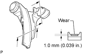
INSPECT CHAIN TENSIONER SLIPPER
-
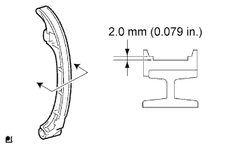
Using vernier calipers, measure the tensioner slipper wear.
Maximum wear 2.0 mm (0.079 in.) If the wear is greater than the maximum, replace the tensioner slipper
-
-
INSPECT CHAIN VIBRATION DAMPER NO.1
-
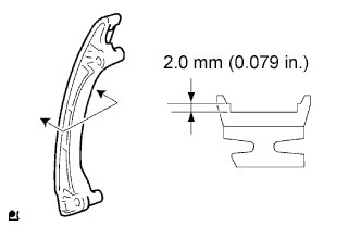
Using vernier calipers, measure the vibration damper wear.
Maximum wear 2.0 mm (0.079 in.) If the wear is greater than the maximum, replace the vibration damper.
-
-
INSPECT TIMING CHAIN GUIDE
-
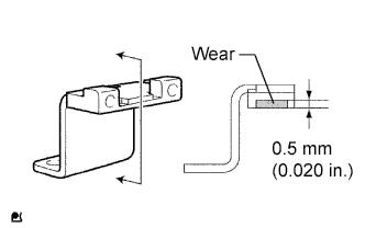
Using vernier calipers, measure the chain guide wear.
Maximum wear 0.5 mm (0.020 in.) If the wear is greater than the maximum, replace the timing chain guide.
-
-
INSPECT CRANKSHAFT TIMING SPROCKET NO.2
-
Wrap the chain around the sprocket.
-
Using vernier calipers, measure the sprocket diameter with the chain.
Minimum sprocket diameter (w/ chain) 96.7 mm (3.807 in.) Tech Tips
The vernier calipers must contact the chain rollers for the measurement.
If the diameter is less than the minimum, replace the chain and sprocket.
-
-
INSPECT BALANCESHAFT DRIVE GEAR SUB-ASSEMBLY
-
Wrap the chain around the sprocket.
-
Using vernier calipers, measure the sprocket diameter with the chain.
Minimum sprocket diameter (w/ chain) 75.9 mm (2.988 in.) Tech Tips
The vernier calipers must contact the chain rollers for the measurement.
If the diameter is less than the minimum, replace the chain and sprocket.
-
-
INSPECT CHAIN VIBRATION DAMPER NO.2
-
Using vernier calipers, measure the vibration damper No.2 wear.
Maximum wear 1.0 mm (0.039 in.) If the wear is greater than the maximum, replace the vibration damper.
-
-
INSPECT CHAIN VIBRATION DAMPER NO.3
-
Using vernier calipers, measure the vibration damper No.3 wear.
Maximum wear 1.0 mm (0.039 in.) If the wear is greater than the maximum, replace the vibration damper.
-
-
INSPECT CHAIN VIBRATION DAMPER NO.4
-
Using vernier calipers, measure the vibration damper No.4 wear.
Maximum wear 1.0 mm (0.039 in.) If the wear is greater than the maximum, replace the vibration damper.
-
-
INSPECT CYLINDER HEAD SET BOLT
-
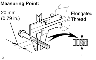
Using vernier calipers, measure the minimum diameter of the elongated thread at the measuring point.
Standard outside diameter 10.76 to 10.97 mm (0.4236 to 0.4319 in.) Minimum outside diameter 10.40 mm (0.4094 in.) If a visual check reveals no excessively thin areas, check the center of the bolt (see illustration) and find the area that has the lowest diameter.
If the diameter is less than the minimum, replace the cylinder head bolt.
-
-
REMOVE VALVE STEM CAP
-
Remove the valve stem caps from the cylinder head.
Tech Tips
Arrange the removed parts in the correct order.
-
-
REMOVE VALVE LASH ADJUSTER ASSEMBLY
-
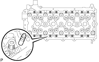
Remove the valve lash adjusters from the cylinder head.
Tech Tips
Arrange the removed parts in the correct order.
-
-
INSPECT VALVE LASH ADJUSTER ASSEMBLY
Note
-
Keep the lash adjuster free from dirt and foreign objects.
-
Only use clean engine oil.
-
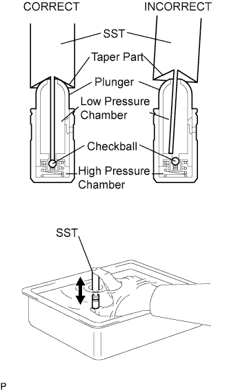
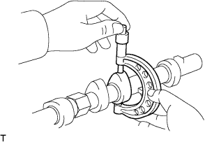
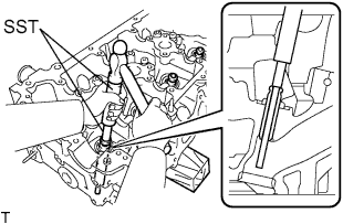
Place the lash adjuster into a container full of engine oil.
-
Insert the SST's tip into the lash adjuster's plunger and use the tip to press down on the checkball inside the plunger.
- SST
- 09276-75010
-
Squeeze the SST and lash adjuster together to move the plunger up and down 5 to 6 times.
-
Check the movement of the plunger and bleed the air.
OK Plunger moves up and down. Note
When bleeding high-pressure air from the compression chamber, make sure that the tip of the SST is actually pressing the checkball as shown in the illustration. If the checkball is not pressed, air will not bleed.
-
After bleeding the air, remove the SST. Then quickly and firmly press the plunger with a finger.
OK Plunger is very difficult to move. If the result is not as specified, replace the lash adjuster.
-
-
REMOVE INTAKE VALVE
-
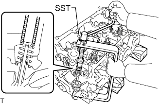
Using SST and wooden blocks, compress the compression spring and remove the valve retainer locks.
- SST
- 09202-70020 ( 09202-00010 )
-
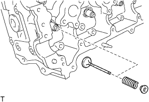
Remove the retainer, compression spring, and valve.
Tech Tips
Arrange the removed parts in the correct order.
-
-
REMOVE EXHAUST VALVE
-
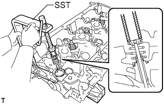
Using SST and wooden blocks, compress the compression spring and remove the valve retainer locks.
- SST
- 09202-70020 ( 09202-00010 )
-
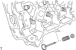
Remove the retainer, compression spring, and valve.
Tech Tips
Arrange the removed parts in the correct order.
-
-
REMOVE VALVE STEM OIL SEAL
-
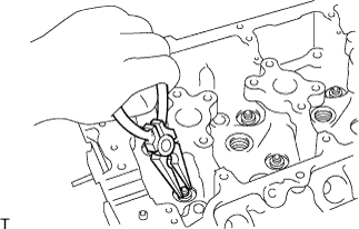
Using needle-nose pliers, remove the oil seals.
-
-
REMOVE VALVE SPRING SEAT
-
Remove the valve spring seats from the cylinder head.
-
-
REMOVE OIL CONTROL VALVE FILTER
-
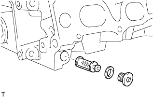
Using an 8 mm hexagon wrench, remove the screw plug.
-
Remove the oil control valve filter and gasket.
-
-
REMOVE W/HEAD STRAIGHT SCREW PLUG NO.1
-
Using a 10 mm hexagon wrench, remove the 3 screw plugs and 3 gaskets.
Note
If water leaks from the w/ head straight screw plug No.1 or the plug corrodes, replace it.
-
-
REMOVE W/HEAD STRAIGHT SCREW PLUG NO.2
-
Using a 19 mm hexagon wrench, remove the screw plug and gasket.
Note
If water leaks from the w/ head straight screw plug No.2 or the plug corrodes, replace it.
-
-
INSPECT CYLINDER HEAD SUB-ASSEMBLY
-
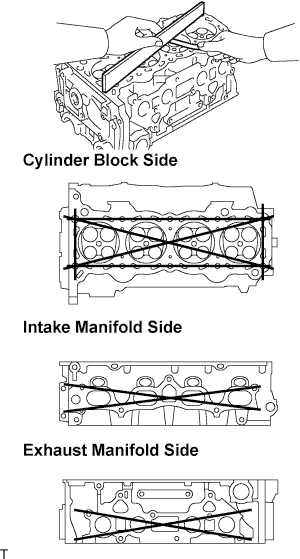
Using a precision straight edge and feeler gauge, measure the warpage of the contact surface of the cylinder block and manifolds.
Maximum warpage 0.05 mm (0.0020 in.) If the warpage is greater than the maximum, replace the cylinder head.
-
Using a dye penetrant, check the intake ports, exhaust ports and cylinder surface for cracks.
If cracked, replace the cylinder head.
-
-
INSPECT INTAKE VALVE SEATS
-
Apply a light coat of prussian blue (or white lead) to the valve face.
-
Lightly press the valve face against the valve seat.
-
Check the valve face and valve seat by using the following procedure.
-
If prussian blue appears around the entire valve face, the valve face is concentric. If not, replace the valve.
-
If prussian blue appears around the entire valve seat, the guide and valve face are concentric. If not, resurface the valve seat.
-
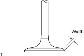
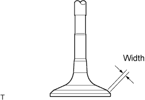
Check that the valve seat contacts in the middle of the valve face with the width between 1.0 and 1.4 mm (0.039 and 0.055 in.).
-
-
-
INSPECT EXHAUST VALVE SEATS
-
Apply a light coat of prussian blue (or white lead) to the valve face.
-
Lightly press the valve face against the valve seat.
-
Check the valve face and valve seat by using the following procedure.
-
If prussian blue appears around the entire valve face, the valve face is concentric. If not, replace the valve.
-
If prussian blue appears around the entrire valve seat, the guide and valve face are concentric. If not, resurface the valve seat.
-
Check that the valve seat contacts in the middle of the valve face with the width between 1.0 and 1.4 mm (0.039 and 0.055 in.).
-
-
-
REPAIR INTAKE VALVE SEATS
Note
Keep the lip free from foreign matter.
-
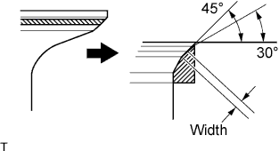
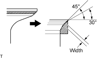
If the seating is too high on the valve face, use 30° and 45° cutters to correct the seat.
-
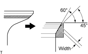
If the seating is too low on the valve face, use 60° and 45° cutters to correct the seat.
-
Handrub the valve and valve seat with an abrasive compound.
-
Check the valve seating position.
-
-
REPAIR EXHAUST VALVE SEATS
Note
Keep the lip free from foreign matter.
-
If the seating is too high on the valve face, use 30° and 45° cutters to correct the seat.
-
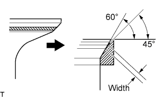
If the seating is too low on the valve face, use 60° and 45° cutters to correct the seat.
-
Handrub the valve and valve seat with an abrasive compound.
-
Check the valve seating position.
-
-
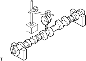
INSPECT CAMSHAFT
-
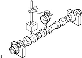
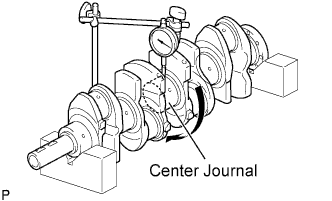
Check the camshaft for runout.
-
Place the camshaft on V-blocks.
-
Using a dial indicator, measure the circle runout at the center journal.
Maximum circle runout 0.03 mm (0.0012 in.) If the circle runout is greater than the maximum, replace the camshaft.
-
-
Using a micrometer, measure the cam lobe height.
Standard cam lobe height 42.855 to 42.955 mm (1.6872 to 1.6911 in.) Minimum cam lobe height 42.855 mm (1.6872 in.) If the cam lobe height is less than the minimum, replace the camshaft.
-
Using a micrometer, measure the journal diameter.
Standard journal diameter Journal Diameter No.1 journal 35.949 to 35.965 mm (1.4153 to 1.4159 in.) Other journal 26.959 to 26.975 mm (1.0614 to 1.0620 in.) If the journal diameter is not as specified, check the oil clearance.
-
-
INSPECT NO. 2 CAMSHAFT
-
Check the camshaft for runout.
-
Place the camshaft on V-blocks.
-
Using a dial indicator, measure the circle runout at the center journal.
Maximum circle runout 0.03 mm (0.0012 in.) If the circle runout is greater than the maximum, replace the camshaft.
-
-
Using a micrometer, measure the cam lobe height.
Standard cam lobe height 42.854 to 42.954 mm (1.687 to 1.6911 in.) Minimum cam lobe height 42.854 mm (1.6872 in.) If the cam lobe height is less than the minimum, replace the camshaft.
-

Using a micrometer, measure the journal diameter.
Standard journal diameter Journal Diameter No.1 journal 35.949 to 35.965 mm (1.4153 to 1.4159 in.) Other journal 26.959 to 26.975 mm (1.0614 to 1.0620 in.) If the journal diameter is not as specified, check the oil clearance.
-
-
INSPECT CAMSHAFT THRUST CLEARANCE
-
Install the camshafts (See reassembly, step 49).
Standard thrust clearance 0.10 to 0.24 mm (0.004 to 0.009 in.) Maximum thrust clearance 0.26 mm (0.010 in.) If the thrust clearance is greater than the maximum, replace the cylinder head. If the thrust surface is damaged, replace the camshaft.
-
-
INSPECT CAMSHAFT OIL CLEARANCE
-
Clean the bearing caps and camshaft journals.
-
Place the camshafts on the cylinder head.
-
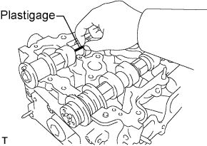
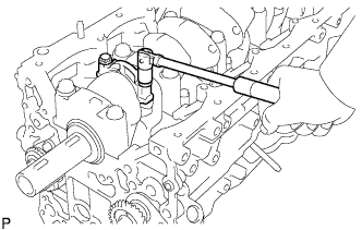
Lay a strip of Plastigage across each of the camshaft journals.
-
Install the bearing caps (See reassembly, step 49).
- Torque:
- 16 N*m { 160 kgf*cm, 11 ft.*lbf }
Note
Do not turn the camshaft.
-
Remove the bearing caps (See step 21).
-
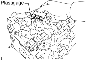
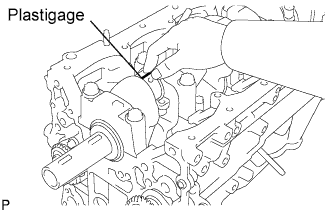
Measure the Plastigage at its widest point.
Standard journal diameter Journal Diameter No.1 journal 0.035 to 0.072mm (0.0014 to 0.0029 in.) Other journal 0.025 to 0.062mm (0.0010 to 0.0024 in.) Maximum oil clearance 0.08 mm (0.003 in.) If the oil clearance is greater than the maximum, replace the camshaft. If necessary, replace the cylinder head.
-
Completely remove the Plastigage.
-
-
INSPECT INNER COMPRESSION SPRING
-
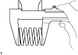
Using vernier calipers, measure the free length of the inner compression spring.
Free length 48.53 mm (1.9106 in.) If the free length is not as specified, replace the spring.
-
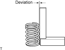
Using a steel square, measure the deviation of the inner compression spring.
Maximum deviation 1.5 mm (0.059 in.) Maximum angle (reference) 2° If the deviation is greater than the maximum, replace the spring.
-
-
INSPECT INTAKE VALVE
-
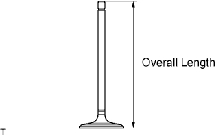
Using vernier calipers, measure the valve's overall length.
Standard overall length 106.26 mm (4.1835 in.) Minimum overall length 105.96 mm (4.1716 in.) If the overall length is less than the minimum, replace the valve.
-
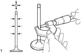
Using a micrometer, measure the diameter of the valve stem.
Valve stem diameter 5.470 to 5.485 mm (0.2154 to 0.2159 in.) -
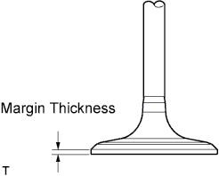
Using vernier calipers, measure the valve head margin thickness.
Standard margin thickness 1.05 to 1.45 mm (0.0413 to 0.0571 in.) Minimum margin thickness 0.50 mm (0.0197 in.) If the overall length is less than the minimum, replace the valve.
-
-
INSPECT EXHAUST VALVE
-
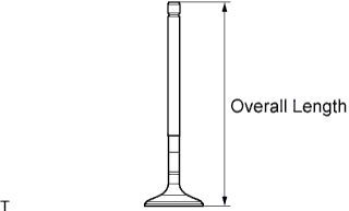
Using vernier calipers, measure the valve's overall length.
Standard overall length 106.74 mm (4.2024 in.) Minimum overall length 106.44 mm (4.1905 in.) If the overall length is less than the minimum, replace the valve.
-
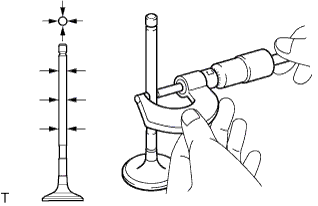
Using a micrometer, measure the diameter of the valve stem.
Valve stem diameter 5.465 to 5.480 mm (0.2151 to 0.2157 in.) -
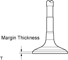
Using vernier calipers, measure the valve head margin thickness.
Standard margin thickness 1.2 to 1.6 mm (0.0472 to 0.0630 in.) Minimum margin thickness 0.50 mm (0.0197 in.) If the margin thickness is less than the minimum, replace the valve.
-
-
INSPECT VALVE GUIDE BUSHING
-
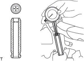
Using a caliper gauge, measure the inside diameter of the guide bush.
Bush inside diameter 5.510 to 5.530 mm (0.2169 to 0.2177 in.) -
Subtract the valve stem diameter measurement from the guide bush inside diameter measurement.
Standard oil clearance 0.025 to 0.060 mm (0.0010 to 0.0024 in.) (Intake) 0.030 to 0.065 mm (0.0012 to 0.0026 in.) (Exhaust) Maximum oil clearance 0.08 mm (0.0032 in.) (Intake) 0.10 mm (0.0039 in.) (Exhaust) If the clearance is greater than the maximum, replace the intake valve and intake guide bush (See disassembly, step 80 and reassembly, step 19).
If the clearance is greater than the maximum, replace the exhaust valve and exhaust guide bush (See disassembly, step 81 and reassembly, step 19).
-
-
REMOVE INTAKE VALVE GUIDE BUSH
-

Heat the cylinder head to 80 to 100°C (176 to 212°F)
-
Place the cylinder head on wooden blocks.
-
Using SST and a hammer, tap out the guide bush.
- SST
- 09201-10000 ( 09201-01050 )
- 09950-70010 ( 09951-07100 )
-
-
REMOVE EXHAUST VALVE GUIDE BUSH
-
Heat the cylinder head to 80 to 100°C (176 to 212 °F).
-
Place the cylinder head on wooden blocks.
-
Using SST and a hammer, tap out the guide bush.
- SST
- 09201-10000 ( 09201-01050 )
- 09950-70010 ( 09951-07100 )
-
-
INSPECT CONNECTING ROD THRUST CLEARANCE
-
Using a dial indicator, measure the thrust clearance while moving the connecting rod back and forth.
Standard thrust clearance 0.150 to 0.350mm (0.0059 to 0.0138 in.) Maximum thrust clearance 0.40 mm (0.016 in.) If the thrust clearance is greater than the maximum, replace the connecting rod assembly(s). If necessary, replace the crankshaft.
-
-
INSPECT CONNECTING ROD OIL CLEARANCE
-
Check that the matchmarks on the connecting rod and cap are aligned to ensure the correct reassembly.
Tech Tips
The matchmarks on the connecting rods and caps are for ensuring the correct reassembly.
-
Remove the 2 connecting rod cap bolts.
-
Using the 2 removed connecting rod cap bolts, remove the connecting rod cap and lower bearing by wiggling the connecting rod cap right and left.
Tech Tips
Keep the lower bearing inserted to the connecting rod cap.
-
Clean the crank pin and bearing.
-
Check the crank pin and bearing for pitting and scratches.
-
Lay a strip of Plastigage on the crank pin.
-
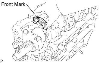
Check that the front mark of the connecting rod cap is facing forward.
-
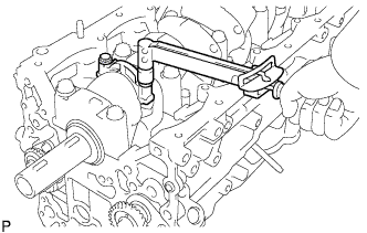
Install the connecting rod cap (See reassembly, step 17).
Note
Do not turn the crankshaft.
-
Remove the 2 bolts and connecting rod cap (See step (b) and (c) above).
-
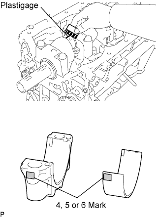
Measure the Plastigage at its widest point.
Standard oil clearance 0.039 to 0.066 mm (0.0015 to 0.0026 in.) Maximum oil clearance 0.066 mm (0.0026 in.) If the oil clearance is greater than the maximum, replace the connecting rod bearings. If necessary, replace the crankshaft.
If replacing a bearing, replace it with one that has the same number as its respective connecting rod cap. Each bearing's standard thickness is indicated by a 4, 5 or 6 mark on its surface.
Standard crankshaft pin diameter Mark Thickness 4 52.987 to 53.000 mm (2.0861 to 2.0866 in.) 5 52.987 to 53.000 mm (2.0861 to 2.0866 in.) 6 52.987 to 53.000 mm (2.0861 to 2.0866 in.) Standard bearing center wall thickness Mark Thickness 4 1.484 to 1.487 mm (0.0584 to 0.0585 in.) 5 1.488 to 1.490 mm (0.0586 to 0.0587 in.) 6 1.491 to 1.493 mm (0.0587 to 0.0588 in.) -
Completely remove the Plastigage.
-
-
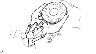
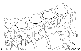
REMOVE PISTON SUB-ASSEMBLY W/CONNECTING ROD
-
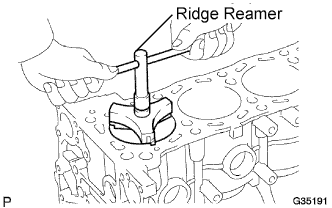
Using a ridge reamer, remove all the carbon from the top of the cylinder.
-
Push the piston, connecting rod assembly and upper bearing through the top of the cylinder block.
Tech Tips
-
Keep the bearing, connecting rod and cap together.
-
Arrange the piston and connecting rod assemblies in the correct order.
-
-
-
REMOVE CONNECTING ROD BEARING
Tech Tips
Arrange the removed parts in the correct order.
-
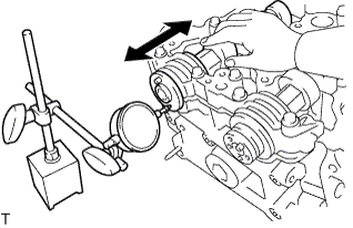
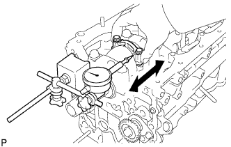
INSPECT CRANKSHAFT THRUST CLEARANCE
-
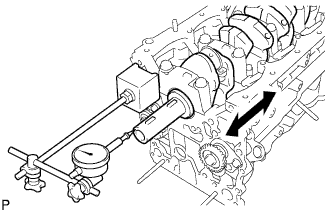
Using a dial indicator, measure the thrust clearance while prying the crankshaft back and forth with a screwdriver.
Standard thrust clearance 0.020 to 0.220 mm (0.0008 to 0.0087 in.) Maximum thrust clearance 0.30 mm (0.0118 in.) If the thrust clearance is greater than the maximum, replace the thrust washers as a set. If necessary, replace the crankshaft.
Thrust Washer thickness 2.440 to 2.490 mm (0.0961 to 0.0980 in.)
-
-
REMOVE CRANKSHAFT
-
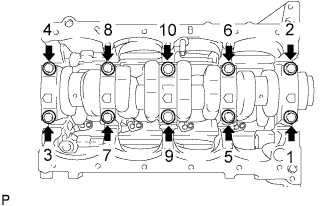
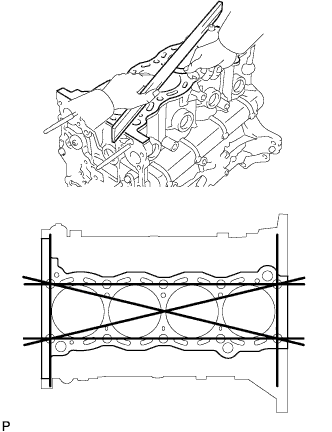
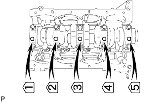
Uniformly loosen the 10 bearing cap bolts in several steps, in the sequence shown in the illustration.
Tech Tips
-
Keep the lower bearings and crankshaft bearing caps together.
-
Arrange the thrust washers in the correct order.
-
-
Lift out the crankshaft.
-
Remove the upper bearings and upper thrust washers from the cylinder block.
Tech Tips
Arrange the main bearing caps, bearings and thrust washers in the correct order.
-
-
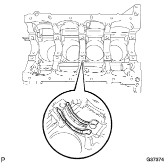
REMOVE CRANKSHAFT BEARING
Tech Tips
Arrange the removed parts in the correct order.
-
REMOVE PISTON RING SET
-
Using a piston ring expander, remove the 2 compression rings.
-
Using a piston ring expander, remove the oil ring rail.
-
Remove the oil ring expander by hand.
Tech Tips
Arrange the piston rings in the correct order.
-
-
REMOVE CYLINDER BLOCK WATER DRAIN COCK SUB-ASSEMBLY
-
Remove the water drain cock sub-assembly from the cylinder block.
-
Remove the water drain cock plug from the water drain cock sub-assembly.
-
-
REMOVE W/PIN PISTON SUB-ASSEMBLY
-
Check the fitting condition between the piston and piston pin.
-
Try to move the piston back and forth on the piston pin.
If any movement is felt, replace the piston and pin as a set.
-
-
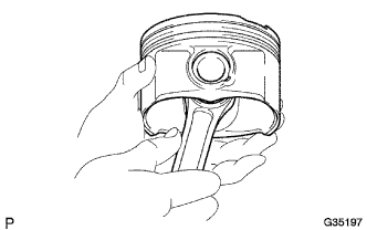
Disconnect the connecting rod from the piston.
-
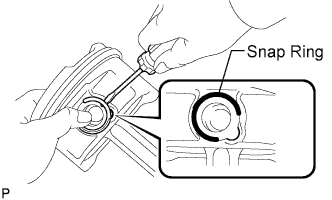
Using a screwdriver, pry off the snap rings from the piston.
-
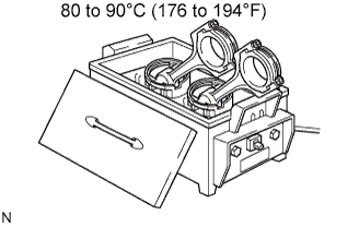
Gradually heat the piston to approximately 80 to 90°C (176 to 194°F).
-
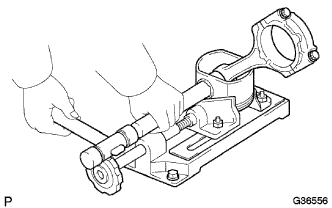
Using a brass bar and plastic hammer, lightly tap out the piston pin and remove the connecting rod.
Tech Tips
-
The piston and pin are a matched set.
-
Arrange the pistons, pins, rings, connecting rods and bearings in the correct order.
-
-
-
-
CLEAN W/PIN PISTON SUB-ASSEMBLY
-
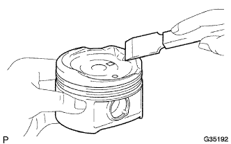
Using a gasket scraper, remove the carbon from the piston top.
-
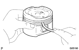
Using a groove cleaning tool or broken ring, clean the piston ring grooves.
-
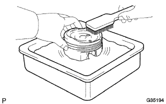
Using solvent and a brush, thoroughly clean the piston.
Note
Do not use a wire brush.
-
-
REMOVE OIL NOZZLE NO.1 SUB-ASSEMBLY
-
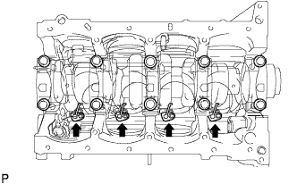
Using a 5 mm hexagon wrench, remove the oil nozzles.
-
-
INSPECT OIL NOZZLE NO.1 SUB-ASSEMBLY
-
Check the oil nozzles for damage or clogging.
If necessary, replace the oil nozzle.
-
-
INSPECT BALANCE SHAFT THRUST CLEARANCE
-
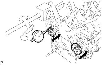
Using a dial indicator, measure the thrust clearance while moving the balanceshaft back and forth.
Standard thrust clearance 0.07 to 0.13 mm (0.0027 to 0.0051 in.) Maximum thrust clearance 0.20 mm (0.0079 in.) If the thrust clearance is greater than the maximum, replace the balanceshaft thrust washer. If necessary, replace the balanceshaft.
-
-
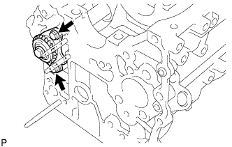
REMOVE NO.1 BALANCESHAFT
-
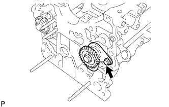
Remove the bolt.
-
Remove the balanceshaft from the cylinder block.
Note
When removing the balanceshaft, make sure to support the balanceshaft with both hands and avoid scratching the balanceshaft bearing on the cylinder block side.
-
-
REMOVE BALANCESHAFT DRIVEN GEAR NO.1
-
Mount the head portion of the balanceshaft in a vise.
Note
Do not damage the balanceshaft.
-
Remove the bolt.
-
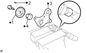
Remove the balanceshaft driven gear No.1 (● 1), sliding key (● 2), balanceshaft thrust washer (● 3) and balanceshaft thrust spacer (● 4).
-
-
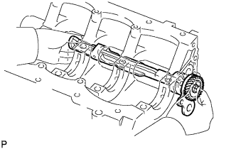
REMOVE NO.2 BALANCESHAFT
-
Remove the 2 bolts.
-
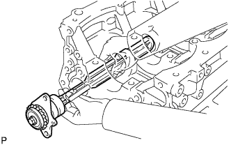
Remove the balanceshaft from the cylinder block.
Note
When removing the balanceshaft, make sure to support the balanceshaft with both hands and avoid scratching the balanceshaft bearing on the cylinder block side.
-
-
REMOVE BALANCESHAFT DRIVEN GEAR NO.2
-
Mount the head portion of the balanceshaft in a vise.
Note
Do not damage the balanceshaft.
-
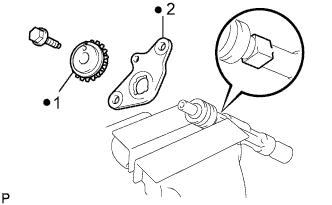
Remove the bolt.
-
Remove the balanceshaft driven gear No.2 (● 1) and balanceshaft thrust washer No.2 (● 2).
-
-
INSPECT CYLINDER BLOCK FOR WARPAGE
-
Using a precision straight edge and feeler gauge, measure the warpage of the contact surface of the cylinder head gasket.
Maximum warpage 0.05 mm (0.0020 in.) If the warpage is greater than the maximum, replace the cylinder block.
-
Visually check the cylinder for vertical scratches.
If deep scratches are present, rebore all the 4 cylinders. If necessary, replace the cylinder block.
-
-
INSPECT CYLINDER BORE
-
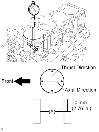
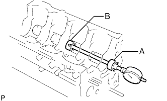
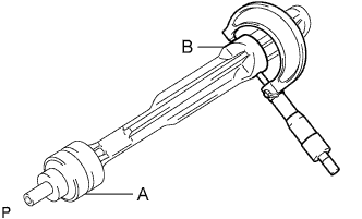
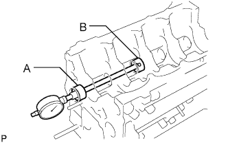
Using a cylinder gauge, measure the cylinder bore diameter at positions A in the thrust and axial directions.
Standard diameter 94.990 to 95.003 mm (3.7398 to 3.7403 in.) Maximum difference diameter 0.2 mm (0.008 in.) If the diameter is greater than the maximum, rebore all the 4 cylinders. If necessary, replace the cylinder block.
-
Inspect the cylinder ridge.
If the wear is less than 0.2 mm (0.008 in.), using a ridge reamer, grind the top of the cylinder.
-
-
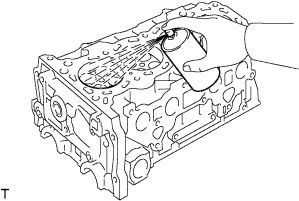
CLEAN CYLINDER BLOCK
-
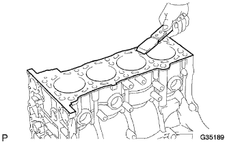
Using a gasket scraper, remove all the gasket material from the top surface of the cylinder block.
-
Using a soft brush and solvent, thoroughly clean the cylinder block.
-
-
INSPECT PISTON DIAMETER
-
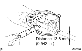
Using a micrometer, measure the piston diameter at right angles to the piston center line where the distance from the piston end is as specified.
Distance 13.8 mm (0.543 in.) Piston diameter Diameter Standard 94.940 to 94.950 mm (3.7378 to 3.7382 in.)
-
-
INSPECT PISTON OIL CLEARANCE
-
Measure the cylinder bore diameter in the thrust direction (See step 101).
-
Subtract the piston diameter measurement from the cylinder bore diameter measurement.
Standard oil clearance 0.019 to 0.052 mm (0.0007 to 0.0020 in.) If the oil clearance is greater than the standard, replace all the pistons and rebore all the cylinders. If necessary, replace the cylinder block.
Tech Tips
-
Bore all the cylinders for the O/S piston outside diameter.
-
Replace all the piston rings with ones to match the O/S pistons.
-
-
If the oil clearance is greater than the standard:
-
Prepare 4 new O/S pistons.
O/S 0.50 piston diameter 95.440 to 95.450 mm (3.7575 to 3.7579 in.) -
Using a micrometer, measure the piston diameter at right angles to the piston center line where the distance from the piston end is as specified.
Distance 13.8 mm (0.543 in.) -
Calculate the amount each cylinder is to be rebored as follows:
Size to be rebored = P + C - H P Piston diameter C Piston clearance: 0.019 to 0.052 mm (0.0007 to 0.0020 in.) H Allowance for honing: 0.02 mm (0.0008 in.) or less -
Bore and hone the cylinders to calculated dimensions.
Maximum honing 0.02 mm (0.0008 in.) Note
Excess honing will destroy the finished roundness.
-
-
-
INSPECT RING GROOVE CLEARANCE
-
Using a feeler gauge, measure the clearance between a new piston ring and the wall of the ring groove.
Ring groove clearance Ring Clearance No. 1 0.020 to 0.075 mm (0.0008 to 0.0030 in.) No. 2 0.020 to 0.065 mm (0.0008 to 0.0026 in.) Oil 0.020 to 0.070 mm (0.0008 to 0.0028 in.) If the clearance is not as specified, replace the piston.
-
-
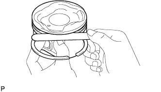
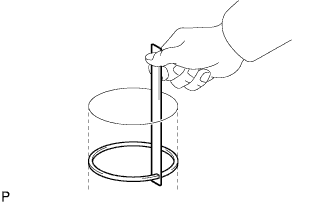
INSPECT PISTON RING END GAP
-
Insert the piston ring into the cylinder bore.
-
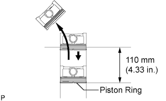
Using a piston, push the piston ring a little beyond the bottom of the ring travel, 110 mm (4.33 in.) from the top of the cylinder block.
-
Using a feeler gauge, measure the end gap.
Standard end gap Ring End gap No. 1 0.22 to 0.34 mm (0.0087 to 0.0134 in.) No. 2 0.45 to 0.57 mm (0.0177 to 0.0224 in.) Oil 0.10 to 0.40 mm (0.0039 to 0.0157 in.) Maximum end gap Ring End gap No. 1 0.90 mm (0.0354 in.) No. 2 1.36 mm (0.0535 in.) Oil 0.75 mm (0.0295 in.) If the end gap is greater than the maximum, replace the piston ring. If the end gap is less than the standard, even with a new piston ring, rebore all the 4 cylinders or replace the cylinder block.
-
-
INSPECT PISTON PIN OIL CLEARANCE
Tech Tips
There is only 1 type of supply part for piston with pin sub-assembly.
-
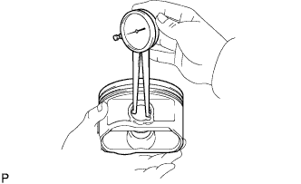
Using a caliper gauge, measure the inside diameter of the piston pin hole.
Piston pin hole inside diameter 22.001 to 22.010 mm (0.8662 to 0.8665 in.) -
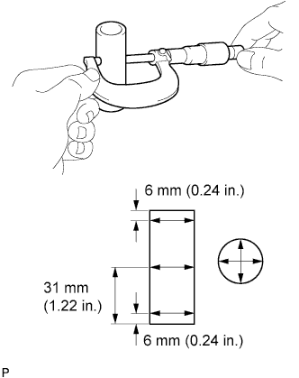
Using a micrometer, measure the piston pin diameter.
Piston pin diameter 21.997 to 22.009 mm (0.8660 to 0.8665 in.) -
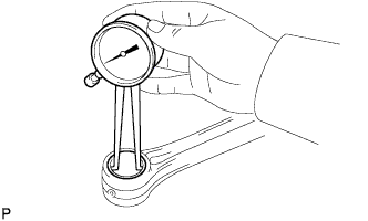
Using a caliper gauge, measure the inside diameter of the connecting rod bushing.
Bushing inside diameter 22.005 to 22.014 mm (0.8663 to 0.8667 in.) -
Subtract the piston pin diameter measurement from the piston pin hole diameter measurement.
Standard oil clearance 0.001 to 0.007 mm (0.00004 to 0.00028 in.) Maximum oil clearance 0.010 mm (0.0004 in.) If the oil clearance is greater than the maximum, replace the piston and piston pin as a set.
-
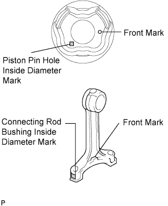
Subtract the piston pin diameter measurement from the bushing inside diameter measurement.
Standard oil clearance 0.005 to 0.011 mm (0.0002 to 0.0004 in.) Maximum oil clearance 0.025 mm (0.0010 in.) -
If the oil clearance is greater than the maximum, replace the bushing. If necessary, replace the connecting rod and piston pin as a set.
-
-
INSPECT CONNECTING ROD SUB-ASSEMBLY
-
Using a rod aligner and feeler gauge, check the connecting rod alignment.
-
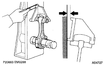
Check for bend.
Maximum bend 0.03 mm (0.0012 in.) per 100 mm (3.94 in.) If the bend is greater than the maximum, replace the connecting rod sub-assembly.
-
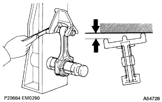
Check for twist.
Maximum twist 0.15 mm (0.0059 in.) per 100 mm (3.94 in.) If the twist is greater than the maximum, replace the connecting rod sub-assembly.
-
-
-
REMOVE CONNECTING ROD SMALL END BUSH
-
Using SST and a press, press out the bush.
- SST
- 09222-30010
-
-
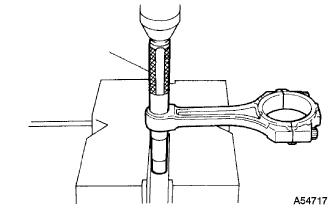
INSPECT CONNECTING ROD BOLT
-
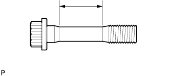
Using vernier calipers, measure the tension portion diameter of the bolt.
Standard diameter 7.2 to 7.3 mm (0.283 to 0.287 in.) Minimum diameter 7.0 mm (0.276 in.) If the diameter is less than the minimum, replace the bolt.
-
-
INSPECT CRANKSHAFT
-
Inspect for circle runout.
-
Place the crankshaft on V-blocks.
-
Using a dial indicator, measure the circle runout at the center journal.
Maximum circle runout 0.03 mm (0.0012 in.) If the circle runout is greater than the maximum, replace the crankshaft.
-
-
Inspect the main journals.
-
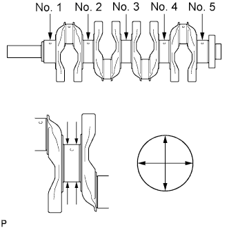
Using a micrometer, measure the diameter of each main journal.
Standard journal diameter Journal Diameter No. 3 journal 59.981 to 59.994 mm (2.3615 to 2.3620 in.) Except No. 3 journal 59.987 to 60.000 mm (2.3619 to 2.3622 in.) If the diameter is not as specified, check the oil clearance (See step 112). If necessary, replace the crankshaft.
-
Check each main journal for taper and out-of- round as shown in the illustration.
Maximum taper and out-of-round 0.005 mm (0.0002 in.) Tech Tips
If the taper and out-of-round is greater than the maximum, replace the crankshaft.
-
-
Inspect the crank pin.
-
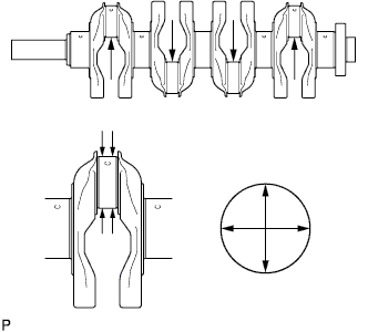
Using a micrometer, measure the diameter of each crank pin.
Diameter 52.989 to 53.002 mm (2.0862 to 2.0867 in.) If the diameter is not as specified, check the oil clearance (See step 83). If necessary, replace the crankshaft.
-
Check each crank pin for taper and out-of-round as shown in the illustration.
Maximum taper and out-of-round 0.003 mm (0.0001 in.) If the taper and out-of-round is greater than the maximum, replace the crankshaft.
-
-
-
INSPECT CRANKSHAFT OIL CLEARANCE
Tech Tips
-
Keep the lower bearings and crankshaft bearing caps together.
-
Arrange the thrust washers in the correct order.
-
Keep the upper crankshaft bearings and upper thrust washers together with the cylinder block.
-
Clean each main journal and bearing.
-
Check each main journal and bearing for pitting and scratches.
If the journal or bearing is damaged, replace the bearing.
-
Place the crankshaft on the cylinder block.
-
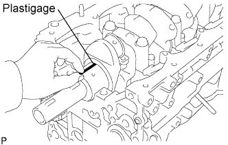
Lay a strip of Plastigage across each journal.
-
Install the 5 crankshaft bearing caps in their proper locations.
-
Install the 5 crankshaft bearing caps with the 10 bolts (See reassembly, step 15).
Note
Do not turn the crankshaft.
-
Remove the 10 bolts and 5 crankshaft bearing caps (See step 87).
-
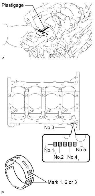
Measure the Plastigage at its widest point.
Standard oil clearance Bearing Cap Standard No. 3 0.030 to 0.055 mm (0.0012 to 0.0022 in.) Others 0.024 to 0.049 mm (0.0009 to 0.0019 in.) Maximum oil clearance 0.10 mm (0.0039 in.) If the oil clearance is greater than the maximum, replace the crankshaft bearing.
If replacing the cylinder block, measure the bearing standard clearance.
If replacing a bearing, first check the number on the cylinder block for the bearing's respective journal. Then replace the bearing with one that has the same number. Each bearing's standard thickness is indicated by a 1, 2 or 3 mark on its surface.
Cylinder block main journal bore diameter Mark Diameter 1 64.004 to 64.010 mm (2.5198 to 2.5201 in.) 2 64.011 to 64.016 mm (2.5201 to 2.5203 in.) 3 64.017 to 64.022 mm (2.5203 to 2.5206 in.) Standard bearing center wall thickness Mark Thickness 1 1.987 to 1.990 mm (0.0782 to 0.0783 in.) 2 1.991 to 1.993 mm (0.0784 to 0.0785 in.) 3 1.994 to 1.996 mm (0.0785 to 0.0786 in.) -
Completely remove the Plastigage.
-
-
INSPECT CRANKSHAFT BEARING CAP SET BOLT
-
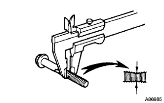
Using vernier calipers, measure the minimum diameter of the compressed thread at the measuring point.
Standard diameter 10.76 to 10.97 mm (0.4236 to 0.4319 in.) Minimum diameter 10.66 mm (0.4197 in.) If the diameter is less than the minimum, replace the bolt.
-
-
INSPECT NO.1 BALANCESHAFT
-
Inspect the diameter of the journal.
-
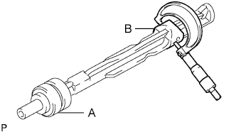
Using a micrometer, measure the diameter of the balanceshaft main journals.
Main journal diameter Journal Diameter A 37.969 to 37.985 mm (1.4948 to 1.4955 in.) B 37.449 to 37.465 mm (1.4744 to 1.4750 in.)
-
-
Inspect the diameter of the bearing.
-
Using a cylinder gauge, measure the inside diameter of the balanceshaft bearing.
Bearing inside diameter Bearing Diameter A 38.025 to 38.045 mm (1.4970 to 1.4978 in.) B 37.525 to 37.545 mm (1.4774 to 1.4781 in.)
-
-
Inspect oil clearance.
-
Subtract the balanceshaft main journal diameter measurement from the balanceshaft bearing inside diameter measurement.
Standard oil clearance Clearance A 0.040 to 0.076 mm (0.0016 to 0.0030 in.) B 0.060 to 0.096 mm (0.0024 to 0.0038 in.) Maximum oil clearance: 0.15 mm (0.0059 in.) If the oil clearance is greater than the maximum, replace the cylinder block and balanceshaft.
-
-
-
INSPECT NO.2 BALANCESHAFT
-
Inspect the diameter of the journal.
-
Using a micrometer, measure the diameter of the balanceshaft main journals.
Main journal diameter Journal Diameter A 37.969 to 37.985 mm (1.4948 to 1.4955 in.) B 37.449 to 37.465 mm (1.4744 to 1.4750 in.)
-
-
Inspect the diameter of the bearing.
-
Using a cylinder gauge, measure the inside diameter of the balanceshaft bearing.
Bearing inside diameter Bearing Diameter A 38.025 to 38.045 mm (1.4970 to 1.4978 in.) B 37.525 to 37.545 mm (1.4774 to 1.4781 in.)
-
-
Inspect oil clearance.
Standard oil clearance Clearance A 0.040 to 0.076 mm (0.0016 to 0.0030 in.) B 0.060 to 0.096 mm (0.0024 to 0.0038 in.) Maximum oil clearance 0.15 mm (0.0059 in.) If the oil clearance is greater than the maximum, replace the cylinder block and balanceshaft.
-