ENGINE UNIT DISASSEMBLY

-
REMOVE OIL FILLER CAP SUB-ASSEMBLY
-
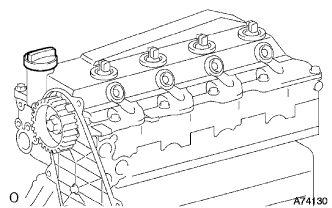
Remove the oil filler cap from the cylinder head cover.
-
-
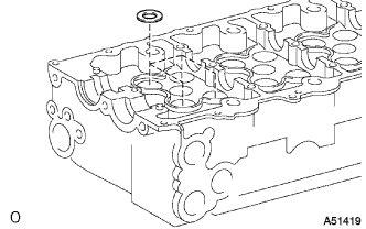
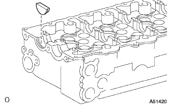
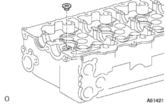
REMOVE NOZZLE HOLDER SEAL
-
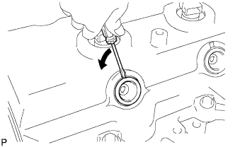
Using a screwdriver, remove the holder seals by prying the portion between the holder seal and the cutout part of the cylinder head.
-
-
REMOVE CYLINDER HEAD COVER SUB-ASSEMBLY
-
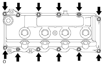
Remove the 10 bolts, 2 nuts, cylinder head cover and the cylinder head cover gasket.
-
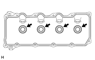
Remove the 4 No. 3 cylinder head cover gaskets from the cylinder head cover.
-
-
REMOVE NOZZLE HOLDER CLAMP NO.1
-
Remove the 4 bolts, 4 washers and 4 nozzle holder clamps.
-
-
REMOVE NOZZLE LEAKAGE PIPE ASSEMBLY
-
Remove the union bolt, 4 hollow screws, nozzle leakage pipe and 5 gaskets from the cylinder head and injector.
Note
Cover the nozzle leakage pipe assembly with a plastic bag to prevent foreign objects from entering to the injector.
-
-
REMOVE INJECTOR ASSEMBLY
-
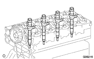
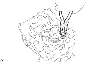
Remove the 4 injectors from the cylinder head.
Tech Tips
Remember the installed locations of each injector before removing them from the cylinder head.
-
-
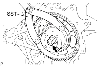
REMOVE CAMSHAFT TIMING PULLEY
-
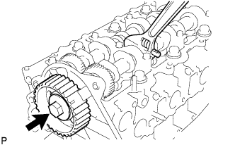
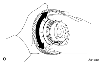
Remove the bolt for the camshaft timing pulley by holding the camshaft with a wrench.
-
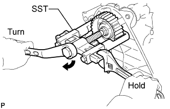
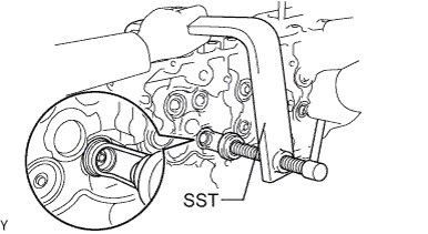
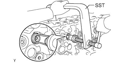
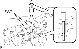
Using SST, remove the camshaft timing pulley and set key.
- SST
- 09950-40011 ( 09951-04010, 09952-04010, 09953-05010, 09957-04010 )
- 09955-04150
-
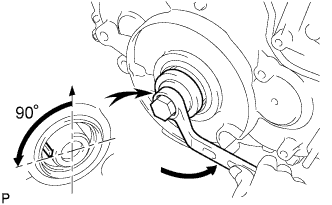
Rotate the crankshaft about 90° counterclockwise from the TDC position to lower the piston.
-
-
REMOVE TIMING BELT NO.2 COVER
-
Remove the nut, 4 bolts and timing belt No.2 cover.
-
-
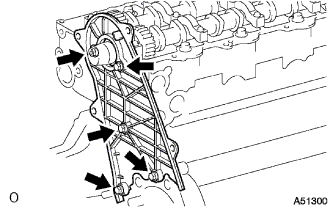
REMOVE NO.2 CAMSHAFT
-
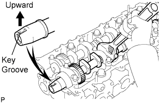
Face the key groove of the camshaft upward by turning the camshaft with a wrench.
-
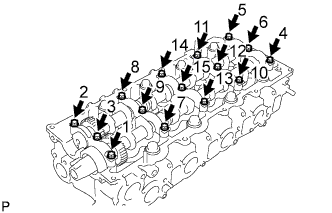
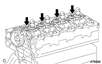
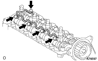
Uniformly loosen the 15 bearing cap bolts in several steps in the sequence shown in the illustration.
-
Remove the 5 bearing caps.
-
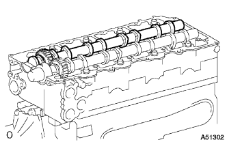
Remove the No.2 camshaft.
-
-
REMOVE CAMSHAFT
-
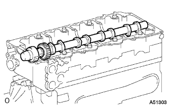
Remove the camshaft.
-
-
REMOVE CAMSHAFT SETTING OIL SEAL
-
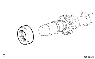
Remove the oil seal from the camshaft.
-
-
REMOVE CYLINDER HEAD SUB-ASSEMBLY
-
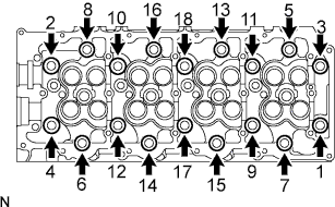
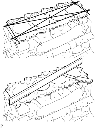
Uniformly loosen and remove the 18 cylinder head bolts in several steps in the sequence shown in the illustration.
Note
Head warpage or cracking could result from removing bolts in an incorrect order.
-
Lift the cylinder head from the dowels on the cylinder block, and place the cylinder head on wooden blocks on a bench.
Tech Tips
If the cylinder head is difficult to lift off, use a screwdriver to pry between the cylinder head and block.
Note
Do not damage the contact surfaces of the cylinder head and cylinder block.
-
Remove the cylinder head gasket from the cylinder block.
-
-
REMOVE WATER PUMP ASSEMBLY
-
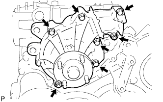
Remove the 5 bolts, 2 nuts, water pump and gasket.
-
-
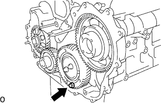
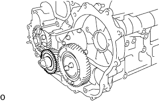
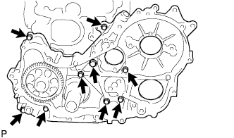
REMOVE TIMING GEAR CASE
-
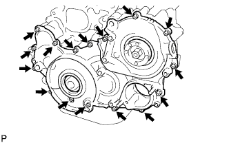
Remove the 14 bolts and 2 nuts.
-
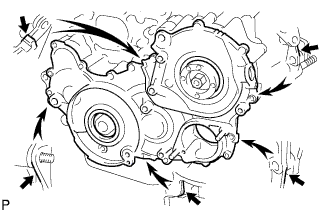
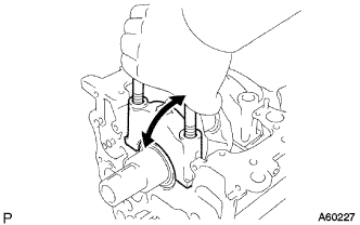
Pry the gear case in the location shown in the illustration.
Note
Do not damage the contact surface.
-
Secure the idler sub-gears to the idler gear with a service bolt.
-
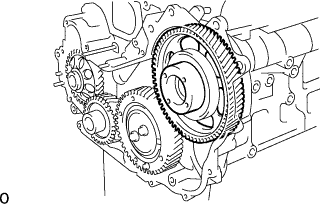
Remove the supply pump gear.
-
Remove the O-ring.
-
-
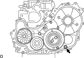
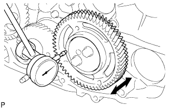
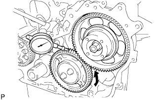
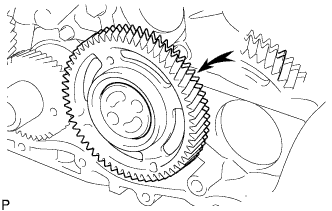
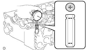
INSPECT BACKLASH OF OIL PUMP GEAR TO CRANKSHAFT TIMING GEAR
-
Using a dial indicator, measure the backlash.
Standard gear backlash 0.02 to 0.15 mm (0.0008 to 0.0060 in.) Maximum gear backlash 0.20 mm (0.0079 in.) If the gear backlash is greater than the maximum, replace the gears as a set.
-
-
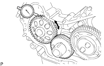
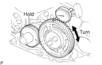
INSPECT IDLE GEAR NO.1 THRUST CLEARANCE
-
Using a dial indicator, measure the thrust clearance.
Standard thrust clearance 0.06 to 0.11 mm (0.0024 to 0.0043 in.) Maximum thrust clearance 0.30 mm (0.0118 in.) If the thrust clearance is greater than the maximum, replace the thrust plate. If necessary, replace the idle gear and/or idle gear shaft.
-
-
REMOVE CRANKSHAFT POSITION SENSOR PLATE NO.1
-
Remove the crankshaft position sensor plate.
-
-
INSPECT BACKLASH OF CRANKSHAFT TIMING GEAR TO IDLE GEAR NO.1
-
Using a dial indicator, measure the backlash.
Standard gear backlash 0.02 to 0.15 mm (0.0008 to 0.0060 in.) Maximum gear backlash 0.20 mm (0.0079 in.) If the gear backlash is greater than the maximum, replace the gears as a set.
-
-
REMOVE CRANKSHAFT TIMING GEAR
-
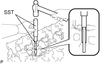
Using SST, remove the crankshaft timing gear.
- SST
- 09950-50013 ( 09951-05010, 09952-05010, 09953-05020, 09954-05011 )
-
-
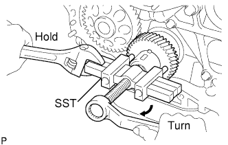
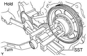
INSPECT BACKLASH OF SUPPLY PUMP GEAR TO IDLE GEAR NO.1.
-
Install the supply pump with the 2 nuts.
- Torque:
- 21 N*m { 214 kgf*cm, 15 ft.*lbf }
-
Using SST, install the supply pump gear with the nut.
- SST
- 09960-10010 ( 09962-01000, 09963-01000 )
- Torque:
- 64 N*m { 652 kgf*cm, 47 ft.*lbf }
-
Using a dial indicator, measure the backlash.
Standard gear backlash 0.02 to 0.15 mm (0.0008 to 0.0060 in.) Maximum gear backlash 0.20 mm (0.0079 in.) If the gear backlash is greater than the maximum, replace the gears as a set.
-
Using SST, remove the nut.
- SST
- 09960-10010 ( 09962-01000, 09963-01000 )
-
Using SST, remove the supply pump gear.
- SST
- 09950-50013 ( 09951-05010, 09952-05010, 09953-05020, 09954-05021 )
-
Remove the 2 nuts and supply pump.
-
-
REMOVE IDLE GEAR THRUST PLATE
-
Remove the 2 bolts and thrust plate.
-
-
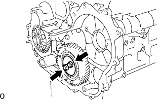
REMOVE IDLE GEAR NO.1
-
Turn the sub gear and align the gear teeth of the idle main gear and sub gear.
-
Remove the idle gear and sub gear.
-
-
REMOVE IDLE GEAR SHAFT NO.1
-
Remove the idle gear shaft.
-
-
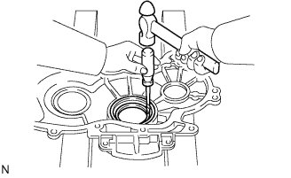
REMOVE TIMING GEAR CASE OR TIMING CHAIN CASE OIL SEAL
-
Using a screwdriver and hammer, tap out the oil seal.
-
-
REMOVE TIMING CHAIN OR BELT COVER OIL SEAL
-
Using a screwdriver and hammer, tap out the oil seal.
-
-
INSPECT IDLE GEAR NO.1
-
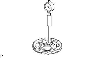
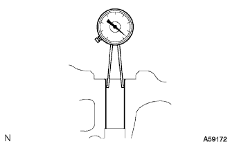
Using a cylinder gauge, measure the inside diameter of the idle gear.
Idle gear inside diameter 44.000 to 44.025 mm (1.7323 to 1.7333 in.) -
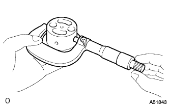
Using a micrometer, measure the diameter of the idle gear shaft.
Idler gear shaft diameter 43.955 to 43.990 mm (1.7305 to 1.7319 in.) -
Subtract the idle gear shaft diameter measurement from the idle gear inside diameter measurement.
Standard oil clearance 0.010 to 0.070 mm (0.0004 to 0.0028 in.) Maximum oil clearance 0.20 mm (0.0079 in.) If the clearance is greater than the maximum, replace the gear and shaft.
-
-
REMOVE IDLE SUB GEAR NO.2
-
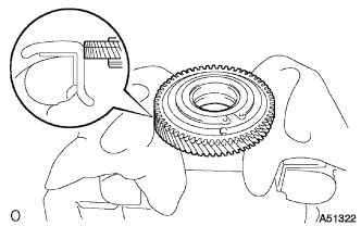
Mount the idler gear in a vise as shown in the illustration.
Note
Do not damage the gear.
-
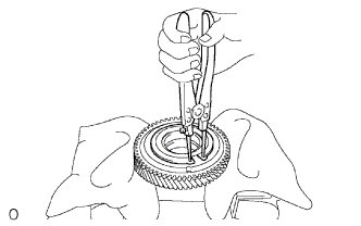
Using snap ring pliers, remove the snap ring.
-
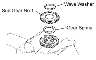
Remove the wave washer, sub gear and gear spring.
-
Remove the idle gear No.1 from the vise.
-
-
REMOVE OIL PAN SUB-ASSEMBLY
-
Remove the drain plug and gasket.
-
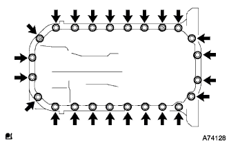
Remove the 22 bolts and 2 nuts.
-
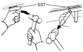
Insert the blade of SST between the oil pan and cylinder block, cut through the applied sealer and remove the oil pan.
Note
-
Do not use SST for the timing belt case side and rear oil seal retainer.
-
Do not damage the oil pan flange.
-
-
-
REMOVE OIL STRAINER SUB-ASSEMBLY
-
Remove the 2 bolts, 2 nuts, oil strainer and gasket.
-
-
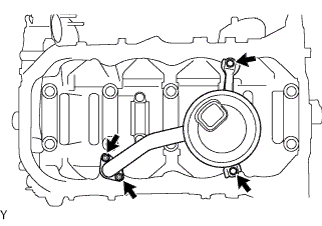
REMOVE TIMING GEAR CASE ASSEMBLY
-
Remove the union bolt and 8 bolts.
-
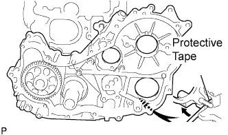
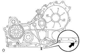
Pry the gear case in the location shown in the illustration, and remove the gear case.
Note
Do not drop the oil pump rotor.
-
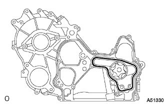
Remove the driven rotor and gasket.
-
Remove the stud bolt.
-
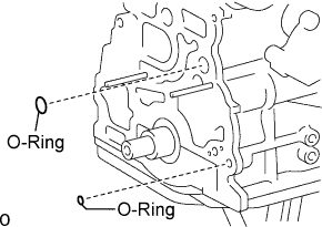
Remove the 2 O-rings.
-
-
REMOVE ENGINE REAR OIL SEAL RETAINER
-
Remove the 5 bolts.
-
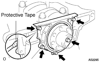
Using a screwdriver, remove the oil seal retainer by prying the portions between the oil seal retainer and cylinder block.
Tech Tips
Tape the screwdriver tip before use.
-
-
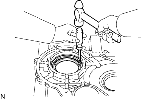
REMOVE ENGINE REAR OIL SEAL
-
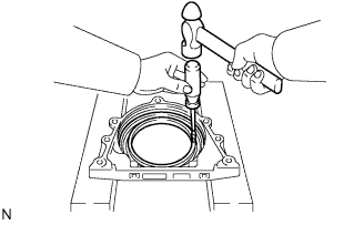
Using a screwdriver and hammer, tap out the oil seal.
-
-
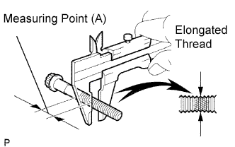
INSPECT CYLINDER HEAD SET BOLT
-
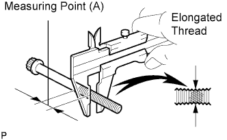
Using vernier calipers, measure the minimum outer diameter of the compressed thread at the measuring point (A).
Standard outer diameter 11.76 to 11.97 mm (0.4630 to 0.4713 in.) Minimum outer diameter 11.6 mm (0.457 in.) If the outer diameter is less than the minimum, replace the bolt.
-
Check for damage to the threads of the cylinder head bolt.
-
Check for damage to the threads of the cylinder block.
-
Check that the 18 cylinder head bolts are installed to the cylinder block smoothly.
-
-
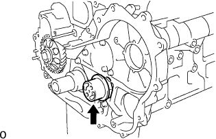
INSPECT SUPPLY PUMP GEAR BEARING
-
Check that the bearing is not rough or worn.
If necessary, replace the bearing.
-
-
REMOVE SUPPLY PUMP GEAR BEARING
-

Using SST, remove the bearing.
- SST
- 09950-40011 ( 09951-04020, 09952-04010, 09953-04030, 09954-04010, 09955-04061, 09957-04010, 09958-04011 )
- 09950-60010 ( 09951-00390, 09951-00460, 09952-06010 )
-
-
REMOVE VALVE LIFTER
-
Remove the valve lifters.
Tech Tips
Arrange the valve lifters in the correct order.
-
-
REMOVE INTAKE VALVE
-
Using SST, compress the compression spring and remove the 2 keepers.
- SST
- 09202-70020 ( 09202-00020 )
-
Remove the spring retainer, compression spring, valve and spring seat.
Tech Tips
Arrange the valves, compression springs, spring seats and spring retainers in the correct order.
-
-
REMOVE EXHAUST VALVE
-
Using SST, compress the compression spring and remove the 2 keepers.
- SST
- 09202-70020 ( 09202-00020 )
-
Remove the spring retainer, compression spring, valve and spring seat.
Tech Tips
Arrange the valves, compression springs, spring seats and spring retainers in the correct order.
-
-
REMOVE VALVE STEM OIL SEAL
-
Using needle-nose pliers, remove the oil seals.
-
-
REMOVE VALVE SPRING SEAT PLATE WASHER
-
Remove the spring seats from the cylinder head.
-
-
REMOVE SEMICIRCULAR PLUG
-
Remove the semicircular plug from the cylinder head.
-
-
REMOVE STRAIGHT SCREW PLUG NO.1
-
Using a 6 mm hexagon wrench, remove the screw plug.
Note
If water leaks from the w/ head straight screw plug No.1 or the plug corrodes, replace it.
-
-
REMOVE STUD BOLT
-
Remove the stud bolts from the cylinder head.
Note
If the stud bolt is deformed or the threads are damaged, replace it.
-
-
REMOVE RING PIN
-
Remove the ring pins from the cylinder head.
Note
It is not necessary to remove the ring pin unless it is being replaced.
-
-
REMOVE TIGHT PLUG
-
Remove the tight plugs from the cylinder head.
Note
If water leaks from the tight plug or the plug corrodes, replace it.
-
-
CLEAN CYLINDER HEAD ASSEMBLY
-
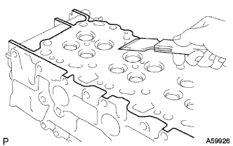
Using a gasket scraper, remove all the gasket material from the cylinder block contact surface.
Note
Do not scratch the cylinder block contact surface.
-
Using a wire brush, remove all the carbon from the combustion chambers.
Note
Do not scratch the cylinder block contact surface.
-
Using a brush and solvent, clean all the guide bushes.
-
Using a soft brush and solvent, thoroughly clean the cylinder head.
-
-
INSPECT CYLINDER HEAD ASSEMBLY
-
Inspect the cylinder head warpage.
-
Using a precision straight edge and feeler gauge, measure the warpage on the surfaces contacting the cylinder block and the manifolds.
Maximum warpage 0.15 mm (0.0059 in.) If warpage is greater than the maximum, replace the cylinder head.
-
-
Inspect the cylinder head for cracks.
-
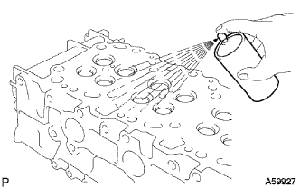
Using a dye penetrant, check the combustion chamber, intake ports, exhaust ports and cylinder block surface for cracks.
If cracked, replace the cylinder head.
-
-
-
INSPECT INTAKE VALVE SEATS
-
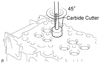
Using a 45° carbide cutter, resurface the valve seats. Clean metal filings from the seats.
-
Check the valve seating position.
-
Apply a light coat of prussian blue (or white lead) to the valve face.
-
Lightly press the valve against the seat. Do not rotate valve.
-
-
Check the valve face and seat for the following:
-
If prussian blue appears around the entire face, the valve is centered. If not, replace the valve.
-
If prussian blue appears around the entire valve seat, the guide and face are centered. If not, resurface the seat.
-
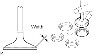
Check that the seat contact is in the middle of the valve face with the width below.
Width 1.2 to 1.6 mm (0.047 to 0.063 in.)
-
-
-
INSPECT EXHAUST VALVE SEATS
-
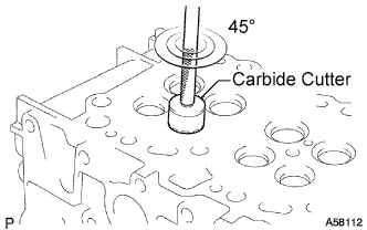
Using a 45° carbide cutter, resurface the valve seats. Clean metal filings from the seats.
-
Check the valve seating position.
-
Apply a light coat of prussian blue (or white lead) to the valve face.
-
Lightly press the valve against the seat. Do not rotate valve.
-
-
Check the valve face and seat for the following:
-
If prussian blue appears around the entire face, the valve is centered. If not, replace the valve.
-
If prussian blue appears around the entire valve seat, the guide and face are centered. If not, resurface the seat.
-
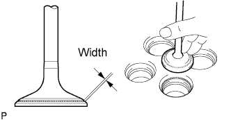
Check that the seat contact is in the middle of the valve face with the width below.
Width 1.6 to 2.0 mm (0.063 to 0.079 in.)
-
-
-
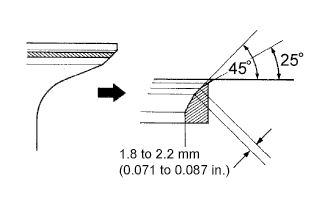
REPAIR INTAKE VALVE SEATS
-
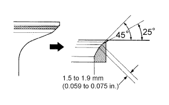
If the seating is too high on the valve face, use 25° and 45° cutters to correct the seat.
-
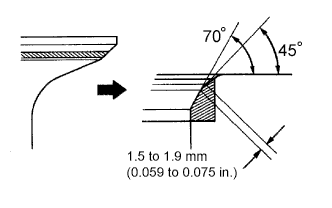
If the seating is too low on the valve face, use 70° and 45° cutters to correct the seat.
-
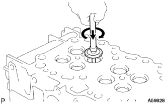
Handrub the valve and valve seat with an abrasive compound.
-
After handrubbing, clean the valve and valve seat.
-
-
REPAIR EXHAUST VALVE SEATS
-
If the seating is too high on the valve face, use 25° and 45° cutters to correct the seat.
-
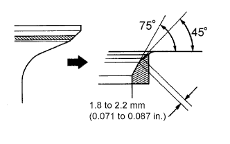
If the seating is too low on the valve face, use 75° and 45° cutters to correct the seat.
-
Handrub the valve and valve seat with an abrasive compound.
-
After handrubbing, clean the valve and valve seat.
-
-
INSPECT CAMSHAFT
-
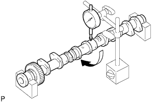
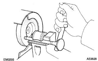
Inspect the circle runout.
-
Place the camshaft on V-blocks.
-
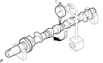
Using a dial indicator, measure the circle runout at the center journal.
Maximum circle runout 0.03 mm (0.0011 in.) If the circle runout is greater than the maximum, replace the camshaft.
-
-
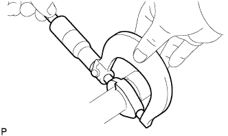
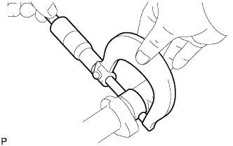
Using a micrometer, measure the cam lobe height.
Standard cam lobe height 46.830 to 46.930 mm (1.8437 to 1.8476 in.) Minimum cam lobe height 46.68 mm (1.8378 in.) If the cam lobe height is less than the minimum, replace the camshaft.
-
Inspect the journal diameter of the camshaft.
-
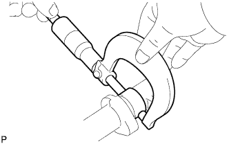
Using a micrometer, measure the journal diameter of the camshaft for the camshaft bearing.
Journal diameter 27.969 to 27.985 mm (1.1011 to 1.1018 in.) If the journal diameter is not as specified, check the oil clearance.
-
-
Check the oil clearance.
-
Clean the bearing caps and journals.
-
Check the bearings for flaking and scoring.
If the bearings are damaged, replace the bearing caps and cylinder head as a set.
-
Install the bearings to the bearing caps and cylinder head.
-
Place the camshaft on the cylinder head.
-
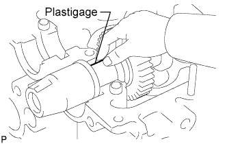
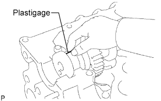
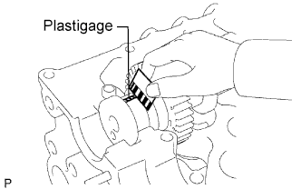
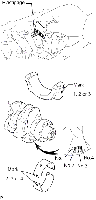
Lay a strip of Plastigage across each of the journals.
-
Install the bearing caps (see reassembly, step 43).
Note
Do not turn the camshaft.
-
Remove the bearing caps.
-
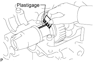
Measure the Plastigage at its widest point.
Standard oil clearance 0.025 to 0.062 mm (0.0010 to 0.0024 in.) Maximum oil clearance 0.10 mm (0.0039 in.) If the oil clearance is greater than the maximum, replace the camshaft. If necessary, replace the bearing cap and cylinder head as a set.
-
Completely remove the Plastigage.
-
Remove the camshaft.
-
-
Check the thrust clearance.
-
Install the camshaft (see reassembly, step 43).
-
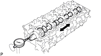
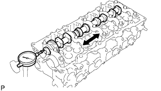
Using a dial indicator, measure the thrust clearance while moving the camshaft back and forth.
Standard thrust clearance 0.035 to 0.185 mm (0.0014 to 0.0073 in.) Maximum thrust clearance 0.25 mm (0.0098 in.) If the thrust clearance is greater than the maximum, replace the camshaft. If necessary, replace the bearing cap and cylinder head as a set.
-
-
-
INSPECT NO.2 CAMSHAFT
-
Inspect the circle runout.
-
Place the camshaft on V-blocks.
-
Using a dial indicator, measure the circle runout at the center journal.
Maximum circle runout 0.03 mm (0.0011 in.) If the circle runout is greater than the maximum, replace the camshaft.
-
-

Using a micrometer, measure the cam lobe height.
Standard cam lobe height 46.870 to 46.970 mm (1.8453 to 1.8492 in.) Minimum cam lobe height 46.72 mm (1.8394 in.) If the cam lobe height is less than the minimum, replace the camshaft.
-
Inspect the journal diameter of the camshaft.
-
Using a micrometer, measure the journal diameter of the camshaft for the camshaft bearing.
Journal diameter 27.969 to 27.985 mm (1.1011 to 1.1018 in.) If the journal diameter is not as specified, check the oil clearance.
-
-
Check the oil clearance.
-
Clean the bearing caps and journals.
-
Check the bearings for flaking and scoring.
If the bearings are damaged, replace the bearing caps and cylinder head as a set.
-
Install the bearings to the bearing caps and cylinder head.
-
Place the camshaft on the cylinder head.
-
Lay a strip of Plastigage across each of the journals.
-
Install the bearing caps (see reassembly, step 43).
Note
Do not turn the camshaft.
-
Remove the bearing caps.
-
Measure the Plastigage at its widest point.
Standard oil clearance 0.025 to 0.062 mm (0.0010 to 0.0024 in.) Maximum oil clearance 0.10 mm (0.0039 in.) If the oil clearance is greater than the maximum, replace the camshaft. If necessary, replace the bearing cap and cylinder head as a set.
-
Completely remove the Plastigage.
-
Remove the camshaft.
-
-
Check the thrust clearance.
-
Install the camshaft (see reassembly, step 43).
-
Using a dial indicator, measure the thrust clearance while moving the camshaft back and forth.
Standard thrust clearance 0.035 to 0.185 mm (0.0014 to 0.0073 in.) Maximum thrust clearance 0.25 mm (0.0098 in.) If the thrust clearance is greater than the maximum, replace the camshaft. If necessary, replace the bearing cap and cylinder head as a set.
-
-
-
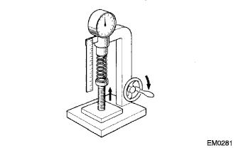
INSPECT INNER COMPRESSION SPRING
-
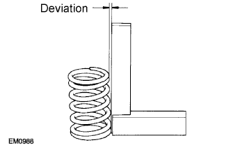
Using a steel square, measure the deviation of the spring.
Maximum deviation 2.0 mm (0.079 in.) If the deviation is greater than the maximum, replace the spring.
-
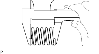
Using vernier calipers, measure the free length of the spring.
Free length 46.5 mm (1.831 in.) If the free length is not as specified, replace the spring.
-
Using a spring tester, measure the tension of the valve spring at the specified installed length.
Installed tension (at 33.1 mm (1.303 in.)): 150.2 to 165.8 N (15.3 to 16.9 kgf, 33.7 to 37.3 lbf) If the tension is not as specified, replace the spring.
-
-
CLEAN INTAKE VALVE
-
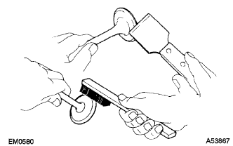
Using a gasket scraper, chip off any carbon from the valve heads.
-
Using a wire brush, thoroughly clean the valves.
-
-
INSPECT INTAKE VALVE
-
Using a micrometer, measure the diameter of the valve stem.
Valve stem diameter 5.970 to 5.985 mm (0.2350 to 0.2356 in.) If the diameter is greater than the maximum, replace the valve and guide bushing.
-
Grind the valve enough to remove pits and carbon.
-
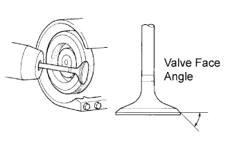
Check that the valve is ground to the correct valve face angle.
Valve face angle 44.5° If the valve is worn, replace the valve.
-
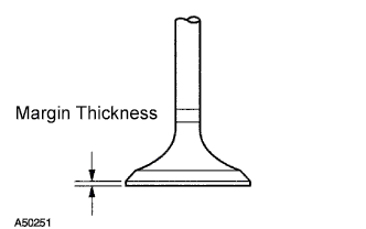
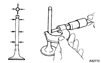
Check the valve head margin thickness.
Standard margin thickness 1.1 mm (0.043 in.) Minimum margin thickness 0.6 mm (0.024 in.) If the margin thickness is less than the minimum, replace the valve.
-
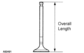
Check the valve overall length.
Standard overall length 105.38 to 105.78 mm (4.1488 to 4.1646 in.) Minimum overall length 104.88 mm (4.1291 in.) If the overall length is less than the minimum, replace the valve.
-
Check the surface of the valve stem tip for wear.
Note
Do not grind off more than the minimum.
If the valve stem tip is worn, resurface the tip with a grinder or replace the valve.
-
-
CLEAN EXHAUST VALVE
-
Using a gasket scraper, chip off any carbon from the valve heads.
-
Using a wire brush, thoroughly clean the valves.
-
-
INSPECT EXHAUST VALVE
-
Using a micrometer, measure the diameter of the valve stem.
Valve stem diameter 5.960 to 5.975 mm (0.2346 to 0.2352 in.) If the diameter is greater than the maximum, replace the valve.
-
Check the valve face angle.
-
Grind the valve enough to remove pits and carbon.
-
Check that the valve is ground to the correct valve face angle.
Valve face angle 44.5 ° If the valve face is worn, replace the valve.
-
-
Check the valve head margin thickness.
Standard margin thickness 1.1 mm (0.043 in.) Minimum margin thickness 0.6 mm (0.024 in.) If the margin thickness is less than the minimum, replace the valve.
-
Check the valve overall length.
Standard overall length 105.57 to 105.97 mm (4.1563 to 4.1720 in.) Minimum overall length 105.07 mm (4.1366 in.) If the overall length is less than the minimum, replace the valve.
-
Check the surface of the valve stem tip for wear.
Note
Do not grind off more than the minimum.
If the valve stem tip is worn, resurface the tip with a grinder or replace the valve.
-
-
INSPECT VALVE GUIDE BUSH OIL CLEARANCE
-
Using a caliper gauge, measure the inside diameter of the guide bush.
Bush inside diameter 6.010 to 6.030 mm (0.2366 to 0.2374 in.) If the journal diameter is not as specified, check the oil clearance.
-
Subtract the valve stem diameter measurement (see steps 56 and 58) from the guide bush inside diameter measurement.
Standard oil clearance Clearance Intake 0.025 to 0.060 mm (0.0010 to 0.0024 in.) Exhaust 0.035 to 0.070 mm (0.0014 to 0.0028 in.) Maximum oil clearance Clearance Intake 0.08 mm (0.0031 in.) Exhaust 0.10 mm (0.0039 in.) If the clearance is greater than the maximum, replace the valve and guide bush.
-
-
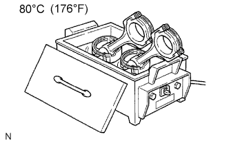
REMOVE INTAKE VALVE GUIDE BUSH
-
Gradually heat the cylinder head to approximately 80 to 100°C (176 to 212°F).
-
Using SST and a hammer, tap out the valve guide bush.
- SST
- 09201-10000 ( 09201-01060 )
- 09950-70010 ( 09951-07100 )
-
-
REMOVE EXHAUST VALVE GUIDE BUSH
-
Gradually heat the cylinder head to approximately 80 to 100°C (176 to 212°F)
-
Using SST and a hammer, tap out the valve guide bush.
- SST
- 09201-10000 ( 09201-01060 )
- 09950-70010 ( 09951-07100 )
-
-
INSTALL INTAKE VALVE GUIDE BUSH
-
Using a caliper gauge, measure the bush bore diameter of the cylinder head.
-
Select a new guide bush (STD or O/S 0.05).
Bush bore diameter Bush size Bush bore diameter Use STD 10.985 to 11.006 mm (0.4325 to 0.4333 in.) Use O/S 0.05 11.035 to 11.056 mm (0.4344 to 0.4353 in.) Tech Tips
-
If the bush bore diameter of the cylinder head is greater than 11.006 mm (0.4333 in.), machine the bush bore diameter to between 11.035 and 11.056 mm (0.4344 to 0.4353 in.).
-
If the bush bore diameter of the cylinder head is greater than 11.056 mm (0.4353 in.), replace the cylinder head.
-
-
Gradually heat the cylinder head to approximately 80 to 100°C (176 to 212°F).
-
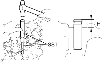
Using SST and a hammer, tap in a new guide bush to the specified protrusion height.
Protrusion height (H) 10.3 to 10.7 mm (0.406 to 0.421 in.) - SST
- 09201-10000 ( 09201-01060 )
- 09950-70010 ( 09951-07100 )
-
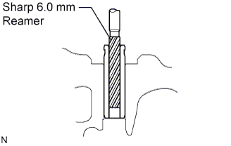
Using a sharp 6.0 mm reamer, ream the guide bush to obtain the standard specified clearance (see step 59) between the guide bush and valve stem.
-
-
INSTALL EXHAUST VALVE GUIDE BUSH
-
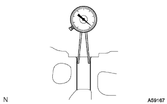
Using a caliper gauge, measure the bush bore diameter of the cylinder head.
-
Select a new guide bush (STD or O/S 0.05).
Bush bore diameter Bush size Bush bore diameter Use STD 10.985 to 11.006 mm (0.4325 to 0.4333 in.) Use O/S 0.05 11.035 to 11.056 mm (0.4344 to 0.4353 in.) Tech Tips
-
If the bush bore diameter of the cylinder head is greater than 11.006 mm (0.4333 in.), machine the bush bore diameter to between 11.035 and 11.056 mm (0.4344 to 0.4353 in.).
-
If the bush bore diameter of the cylinder head is greater than 11.056 mm (0.4353 in.), replace the cylinder head.
-
-
Gradually heat the cylinder head to approximately 80 to 100°C (176 to 212°F).
-
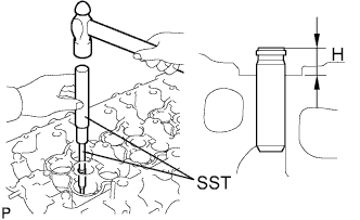
Using SST and a hammer, tap in a new guide bush to the specified protrusion height.
- SST
- 09201-10000 ( 09201-01060 )
- 09950-70010 ( 09951-07100 )
Protrusion height (H) 10.3 to 10.7 mm (0.406 to 0.421 in.) -
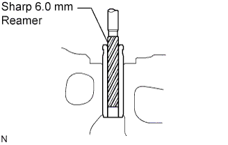
Using a sharp 6.0 mm reamer, ream the guide bush to obtain the standard specified clearance (see step 59) between the guide bush and valve stem.
-
-
INSPECT VALVE LIFTER
-
Using a micrometer, measure the lifter diameter.
Lifter diameter 30.966 to 30.976 mm (1.2191 to 1.2195 in.) -
Using a caliper gauge, measure the lifter bore diameter of the cylinder head.
Lifter bore diameter 31.000 to 31.021 mm (1.2205 to 1.2213 in.) If the lifter diameter is not as specified, check the oil clearance.
-
Subtract the lifter diameter measurement from the lifter bore diameter measurement.
Standard oil clearance 0.024 to 0.055 mm (0.0009 to 0.0022 in.) Maximum oil clearance 0.075 mm (0.0030 in.) If the oil clearance is greater than the maximum, replace the lifter. If necessary, replace the cylinder head.
-
-
REMOVE CYLINDER BLOCK OIL ORIFICE
-
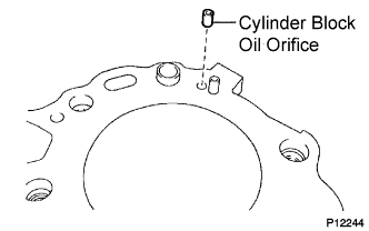
Remove the cylinder block oil orifice from the cylinder block.
-
-
INSPECT CYLINDER BLOCK OIL ORIFICE
-
Check the oil orifice for damage or clogging.
If necessary, replace the oil orifice.
-
-
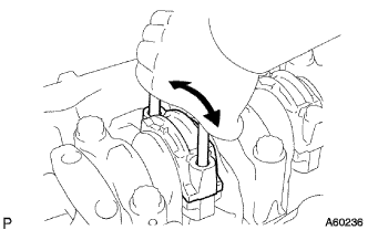
INSPECT CONNECTING ROD THRUST CLEARANCE
-
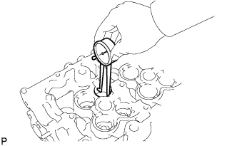
Using a dial indicator, measure the thrust clearance while moving the connecting rod back and forth.
Standard thrust clearance 0.100 to 0.300 mm (0.0039 to 0.0118 in.) Maximum thrust clearance 0.40 mm (0.0157 in.) If the thrust clearance is greater than the maximum, replace the connecting rod assembly. If necessary, replace the crankshaft.
-
-
INSPECT CONNECTING ROD OIL CLEARANCE
-
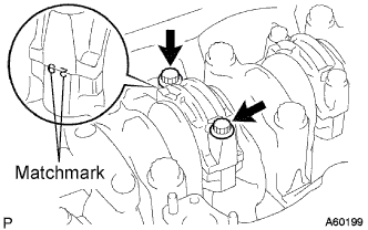
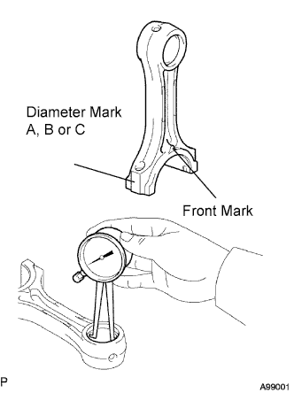
Check the matchmarks on the connecting rod and cap to ensure correct reassembly.
-
Remove the 2 connecting road cap bolts.
-
Using the 2 removed connecting rod bolts, pry the connecting rod cap back and forth, and remove the connecting cap.
Tech Tips
Keep the lower bearing inserted with the connecting rod cap.
-
Clean the crank pin and bearing.
-
Check the crank pin and bearing for pitting and scratches.
If the crank pin or bearing is damaged, replace the bearings. If necessary, grind or replace the crankshaft.
-
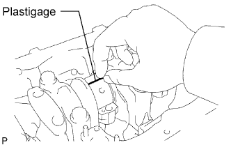
Lay a strip of Plastigage across the crank pin.
-
Install the connecting rod cap with the 2 bolts (see reassembly, step 13).
Note
Do not turn the crankshaft.
-
Remove the 2 bolts, connecting rod cap and lower bearing (see steps (b) and (c) above).
-
Measure the Plastigage at its widest point.
Standard oil clearance Size Clearance STD 0.036 to 0.054 mm (0.0014 to 0.0021 in.) U/S 0.25, U/S 0.50 0.037 to 0.077 mm (0.0015 to 0.0030 in.) Maximum oil clearance 0.10 mm (0.0039 in.) If the oil clearance is greater than the maximum, replace the bearings. If necessary, grind or replace the crankshaft.
Tech Tips
If using a standard bearing, replace it with one that has the same number. If the number of the bearing cannot be determined, select the correct bearing by adding together the numbers imprinted on the crankshaft and connecting rod, then select the bearing with the same number as the total. There are 5 sizes of standard bearings, marked 2, 3, 4, 5 and 6.
EXAMPLE:
Connecting rod cap "3" + Crankshaft "1" =
Total number 4 (Use bearing "4")
Reference Connecting rod big end inner diameter Mark Diameter 1 62.014 to 62.020 mm (2.4415 to 2.4417 in.) 2 62.020 to 62.026 mm (2.4417 to 2.4420 in.) 3 62.026 to 62.032 mm (2.4420 to 2.4422 in.) Crankshaft pin diameter Mark Diameter 1 58.994 to 59.000 mm (2.3226 to 2.3228 in.) 2 58.988 to 58.994 mm (2.3224 to 2.3226 in.) 3 58.982 to 58.988 mm (2.3221 to 2.3224 in.) Standard sized bearing center wall thickness Mark Bearing center wall thickness 2 1.486 to 1.489 mm (0.0585 to 0.0586 in.) 3 1.489 to 1.492 mm (0.0586 to 0.0587 in.) 4 1.492 to 1.495 mm (0.0587 to 0.0589 in.) 5 1.495 to 1.498 mm (0.0589 to 0.0590 in.) 6 1.498 to 1.501 mm (0.0590 to 0.0591 in.) -
Completely remove the Plastigage.
-
-
REMOVE CONNECTING ROD BEARING
-
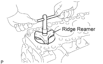
Using a ridge reamer, remove all the carbon from the top of the cylinder.
-
Push the piston, connecting rod assembly and upper bearing through the top of the cylinder block.
Tech Tips
-
Keep the bearings, connecting rod and cap together.
-
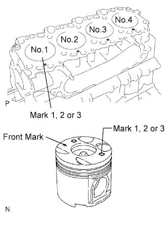
Be sure to organize the removed piston and connecting rod assemblies in such a way that they can be reinstalled exactly as before.
-
-
-
INSPECT PISTON W/CONNECTING ROD
-
Check the fitting condition between the piston and piston pin.
-
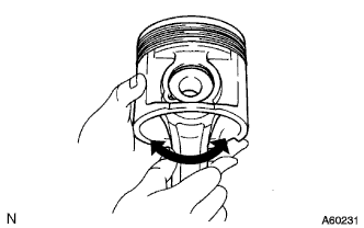
Try to move the piston back and forth on the piston pin.
If any movement is felt, replace the piston and pin with a new piston and pin as a set.
-
-
-
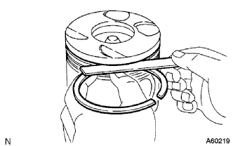
REMOVE PISTON RING SET
-
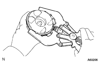
Using a piston ring expander, remove the 2 compression rings.
Tech Tips
Be sure to organize the removed piston rings in such a way that they can be reinstalled exactly as before.
-
Remove the coil and oil ring by hand.
-
-
REMOVE PISTON SUB-ASSEMBLY W/PIN
-
Disconnect the connecting rod from the piston.
-
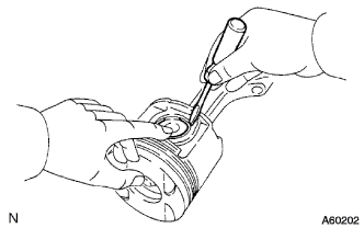
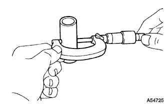
Using a screwdriver, pry off the 2 snap rings from the piston.
-
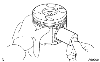
Gradually heat the piston to approximately 80°C (176°F).
-
Using a plastic hammer and brass bar, lightly tap out the piston pin. Then remove the connecting rod.
Tech Tips
-
The piston and pin are a matched set.
-
Be sure to organize the removed pistons, pins, rings, connecting rods and bearings in such a way that the parts can be reinstalled exactly as before.
-
-
-
-
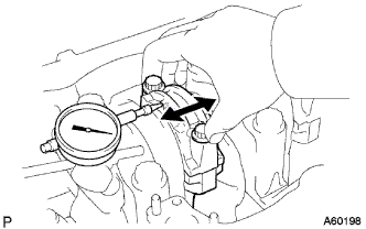
INSPECT CRANKSHAFT THRUST CLEARANCE
-
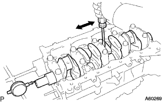
Using a dial indicator, measure the thrust clearance while prying the crankshaft back and forth with a screwdriver.
Standard thrust clearance 0.040 to 0.240 mm (0.0016 to 0.0098 in.) Maximum thrust clearance 0.30 mm (0.0118 in.) If the thrust clearance is greater than the maximum, replace the thrust washers as a set.
Thrust washer thickness Size Thickness STD 2.430 to 2.480 mm (0.0957 to 0.0976 in.) O/S 0.125 2.555 to 2.605 mm (0.1005 to 0.1025 in.) O/S 0.250 2.680 to 2.730 mm (0.1055 to 0.1074 in.)
-
-
INSPECT CRANKSHAFT OIL CLEARANCE
-
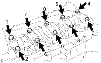
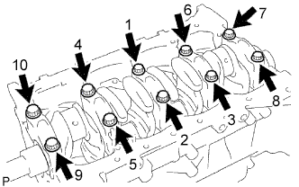
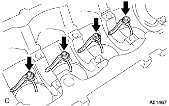
Uniformly loosen and remove the 10 crankshaft bearing cap bolts in several steps, in the sequence shown in the illustration.
-
Using the removed crankshaft bearing cap bolts, pry the cap back and forth, and remove the crankshaft bearing caps, lower crankshaft bearings and lower thrust washers (No. 5 crankshaft bearing cap only).
Tech Tips
-
Keep the lower bearing and crankshaft bearing cap together.
-
Be sure to organize the bearing caps and lower thrust washers in such a way that they can be reinstalled exactly as before.
-
-
Lift out the crankshaft.
Tech Tips
Keep the upper crankshaft bearings and upper thrust washers together with the cylinder block.
-
Clean each crankshaft journal and bearing.
-
Check each crankshaft journal and bearing for pitting and scratches.
If the journal or bearing is damaged, replace the bearings. If necessary, grind or replace the crankshaft.
-
Place the crankshaft on the cylinder block.
-
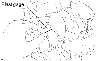
Lay a strip of Plastigage across each journal.
-
Install the 5 crankshaft bearing caps with the 10 bolts (see reassembly, step 12).
Note
Do not turn the crankshaft.
-
Remove the 10 bolts and 5 crankshaft bearing caps (see steps (a) and (b) above).
-
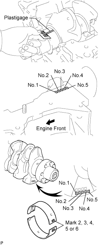
Measure the Plastigage at its widest point.
Standard oil clearance Size Oil clearance STD 0.030 to 0.048 mm (0.0012 to 0.0019 in.) O/S 0.25, O/S 0.50 0.037 to 0.077 mm (0.0015 to 0.0030 in.) Maximum clearance 0.10 mm (0.0039 in.) If the oil clearance is greater than the maximum, replace the bearings. If necessary, grind or replace the crankshaft.
Tech Tips
If replacing the cylinder block sub-assembly, the bearing standard clearance will be within the standard value.
Standard 0.030 to 0.048 mm (0.0012 to 0.0019 in.) Tech Tips
If using a standard bearing, replace it with one having the same number. If the number of the bearing cannot be determined, select the correct bearing by adding together the numbers imprinted on the cylinder block and crankshaft, then select the bearing with the same number as the total. There are 5 sizes of standard bearings, marked 2, 3, 4, 5 and 6.
Reference Cylinder block main journal bore diameter Mark Diameter 1 75.000 to 75.006 mm (2.9528 to 2.9530 in.) 2 75.006 to 75.012 mm (2.9530 to 2.9532 in.) 3 75.012 to 75. 018 mm (2.9532 to 2.9535 in.) Crankshaft journal diameter Mark Diameter 1 69.994 to 70.000 mm (2.7557 to 2.7559 in.) 2 69.988 to 69.994 mm (2.7554 to 2.7557 in.) 3 69.982 to 69.988 mm (2.7552 to 2.7554 in.) Standard sized bearing center wall thickness Mark Bearing center wall thickness 2 2.482 to 2.485 mm (0.0977 to 0.0978 in.) 3 2.485 to 2.488 mm (0.0978 to 0.0980 in.) 4 2.488 to 2.491 mm (0.0980 to 0.0981 in.) 5 2.491 to 2.494 mm (0.0981 to 0.0982 in.) 6 2.494 to 2.497 mm (0.0982 to 0.0983 in.) -
Completely remove the Plastigage.
-
-
REMOVE CRANKSHAFT
-
Lift out the crankshaft.
-
Remove the upper bearings and upper thrust washers from the cylinder block.
Tech Tips
Arrange the main bearing caps, bearings and thrust washers in the correct order
-
-
REMOVE OIL NOZZLE NO.1 SUB-ASSEMBLY
-
Remove the 4 check valves and oil nozzles.
-
-
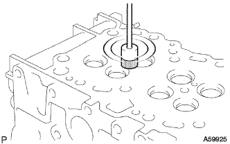
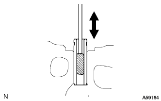
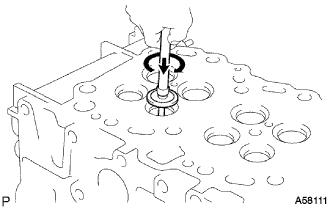
INSPECT OIL CHECK VALVE SUB-ASSEMBLY
-
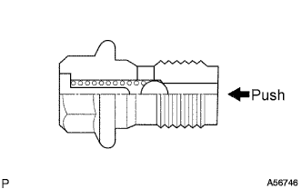
Push the valve with a wooden stick to check if it is stuck.
Tech Tips
If stuck, replace the check valve.
-
-
REMOVE SCREW PLUG
-
Remove the screw plug and gasket.
-
-
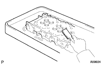
CLEAN CYLINDER BLOCK ASSEMBLY
-
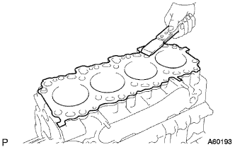
Using a gasket scraper, remove all the gasket material from the top surface of the cylinder block.
-
Using a soft brush and solvent, thoroughly clean the cylinder block.
Note
Protect your eyes when using high pressure compressed air.
-
-
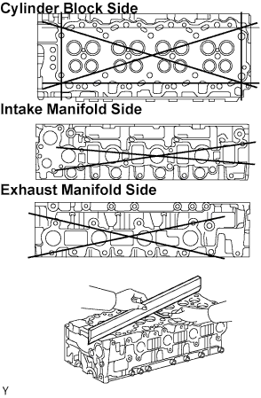
INSPECT CYLINDER BLOCK ASSEMBLY
-
Inspect for warpage.
-
Using a precision straight edge and feeler gauge, measure the warpage on the surface contacting the cylinder head cap.
Maximum warpage 0.10 mm (0.0039 in.) If warpage is greater than the maximum, replace the cylinder block.
-
-
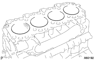
Visually check the cylinder for vertical scratches.
If deep scratches are present, rebore all the 4 cylinders. If necessary, replace the cylinder block.
-
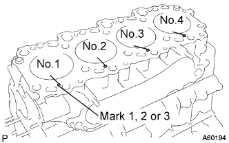
Inspect the cylinder bore diameter.
Tech Tips
There are 3 sizes of the standard cylinder bore diameter, marked 1, 2 and 3 accordingly. The mark is stamped on the lower left rear of the cylinder block.
-
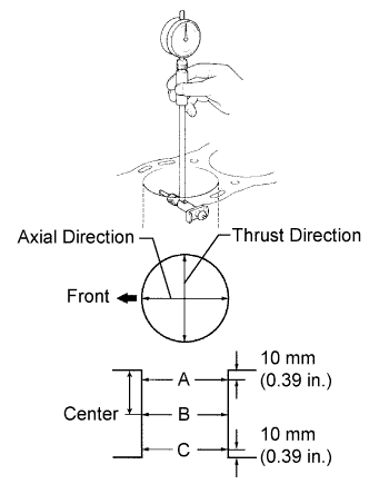
Using a cylinder gauge, measure the cylinder bore diameter at positions A, B and C in the thrust and axial directions.
Standard diameter Mark Diameter 1 92.000 to 92.010 mm (3.6220 to 3.6224 in.) 2 92.010 to 92.020 mm (3.6224 to 3.6228 in.) 3 92.020 to 92.030 mm (3.6228 to 3.6232 in.) Maximum diameter 92.23 mm (3.6311 in.) If the diameter is greater than the maximum, rebore all the 4 cylinders. If necessary, replace the cylinder block.
-
-
Inspect the cylinder ridge.
Tech Tips
If the wear is less than 0.2 mm (0.008 in.), using a ridge reamer, grind the top of the cylinder.
-
-
CLEAN PISTON
-
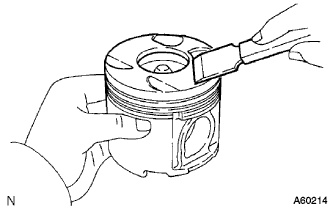
Using a gasket scraper, remove the carbon from the piston top.
-
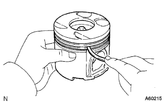
Using a groove cleaning tool or broken ring, clean the piston ring grooves.
-
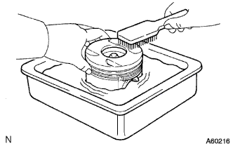
Using solvent and a brush, thoroughly clean the piston.
Note
Do not use a wire brush.
-
-
INSPECT PISTON SUB-ASSEMBLY W/PIN
Tech Tips
-
When replacing the piston sub-assembly w/pin with a supply part, there are a number of piston diameter size to choose from, but there is only one size of piston pin diameter.
-
There are 3 sizes of the standard piston diameter, marked "1", "2" and "3" accordingly. The mark is stamped on the piston top.
-
Inspect the piston oil clearance.
-
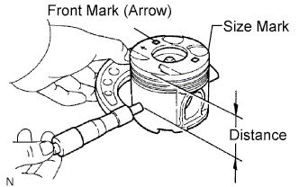
Using a micrometer, measure the piston diameter at right angles to the piston center line, the indicated distance from the piston head.
Distance 65 mm (2.5591 in.) Piston diameter - - Diameter STD Mark 1 91.920 to 91.930 mm (3.6189 to 3.6193 in.) STD Mark 2 91.931 to 91.940 mm (3.6193 to 3.6197 in.) STD Mark 3 91.941 to 91.950 mm (3.6197 to 3.6201 in.) STD O/S 0.50 92.42 to 92.45 mm (3.6386 to 3.6398 in.) Tech Tips
The piston should be installed to the block which has the same mark with the piston.
-
Measure the cylinder bore diameter in the thrust directions (see step 80).
-
Subtract the piston diameter measurement from the cylinder bore diameter measurement.
Standard oil clearance 0.070 to 0.090 mm (0.0028 to 0.0035 in.) Maximum oil clearance 0.16 mm (0.0063 in.) If the oil clearance is greater than the maximum, replace all the 4 pistons and rebore all the 4 cylinders. If necessary, replace the cylinder block.
Tech Tips
-
Use a piston with the same number mark as the cylinder diameter marked on the cylinder block.
-
Bore all the 4 cylinders for the O/S piston outside diameter.
-
Replace all the piston rings with ones to match the O/S pistons.
-
-
-
Prepare 4 new O/S pistons.
O/S 0.50 piston diameter 92.42 to 92.45 mm (3.6386 to 3.6398 in.) -
Using a micrometer, measure the piston diameter at right angles to the piston center line, the indicated distance from the piston head.
Distance 65 mm (2.5591 in.) -
Calculate the amount each cylinder is to be rebored as follows:
Size to be rebored = P + C - H: P Piston diameter C Piston clearance: 0.070 to 0.090 mm (0.0028 to 0.0035 in.) H Allowance for honing: 0.02 mm (0.0008 in.) or less -
Bore and hone the cylinders to calculated dimensions.
Maximum honing 0.02 mm (0.0008 in.) Note
Excess honing will destroy the finished roundness.
-
Using a micrometer, measure the piston pin diameter.
Piston pin diameter Mark Diameter A 33.996 to 34.000 mm (1.3384 to 1.3385 in.) B 34.001 to 34.004 mm (1.3385 to 1.3387 in.) C 34.005 to 34.008 mm (1.3387 to 1.3388 in.) -
Inspect the piston pin fit.
-
Heat the piston to 80°C (176°F), and push the piston pin into the piston pin hole with your thumb.
If the pin can be installed at a lower temperature, replace the piston and pin as a set.
-
-
-
INSPECT PISTON RING SET
-
Inspect the piston ring groove clearance.
-
Using a feeler gauge, measure the clearance between a new piston ring and the wall of the ring groove.
Standard groove clearance Ring Groove clearance No. 1 0.060 to 0.100 mm (0.0024 to 0.0039 in.) No. 2 0.050 to 0.090 mm (0.0020 to 0.0035 in.) Oil 0.030 to 0.075 mm (0.0012 to 0.0030 in.) Maximum groove clearance 0.20 mm (0.0079 in.) If the clearance is greater than the maximum, replace the piston.
-
-
Inspect the piston ring end gap.
-
Insert the piston ring into the cylinder bore.
-
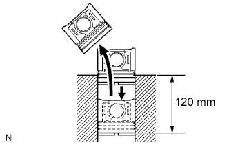
Using a piston, push the piston ring a little beyond the bottom of the ring travel, 120 mm (4.72 in.) from the top of the cylinder block.
-
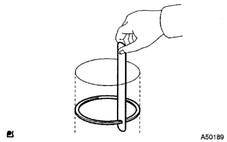
Using a feeler gauge, measure the end gap.
Standard end gap Ring End gap No. 1 0.390 to 0.510 mm (0.0106 to 0.0154 in.) No. 2 0.470 to 0.620 mm (0.0185 to 0.0244 in.) Oil 0.200 to 0.400 mm (0.0079 to 0.0157 in.) Maximum end gap Ring End gap No. 1 1.21 mm (0.0476 in.) No. 2 1.44 mm (0.0567 in.) Oil 1.22 mm (0.0480 in.) If the end gap is greater than the maximum, replace the piston ring. If the end gap is greater than the maximum, even with a new piston ring, rebore all the 4 cylinders or replace the cylinder block.
-
-
-
INSPECT CONNECTING ROD SUB-ASSEMBLY
-
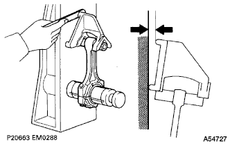
Using a rod aligner and feeler gauge, check the connecting rod alignment.
-
Check if the rod is bent.
Maximum bend 0.03 mm (0.0012 in.) per 100 mm (3.94 in.) If bend is greater than the maximum, replace the connecting rod sub-assembly.
-
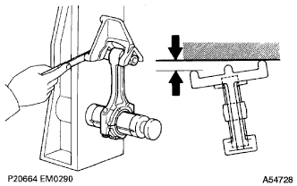
Check if the rod is twisted.
Maximum twist 0.15 mm (0.0059 in.) per 100 mm (3.94 in.) If twist is greater than the maximum, replace the connecting rod sub-assembly.
-
-
-
INSPECT PISTON PIN OIL CLEARANCE
Tech Tips
When replacing the piston sub-assembly w/pin with a supply part, there are a number of piston diameter size to choose from, but there is only one size of piston pin diameter.
-
Inspect the piston pin oil clearance.
-
Using a caliper gauge, measure the inside diameter of the connecting rod bush.
Connecting rod bush inside diameter Mark Diameter A 34.012 to 34.016 mm (1.3390 to 1.3392 in.) B 34.017 to 34.020 mm (1.3392 to 1.3393 in.) C 34.021 to 34.024 mm (1.3394 to 1.3395 in.) -
Subtract the piston pin diameter measurement (see step 82) from the bush inside diameter measurement.
Standard oil clearance 0.012 to 0.020 mm (0.0005 to 0.0009 in.) Maximum oil clearance 0.03 mm (0.0012 in.) If the oil clearance is greater than the maximum, replace the bush. If necessary, replace the piston and piston pin with a new piston and pin set.
-
-
-
REMOVE CONNECTING ROD SMALL END BUSH
-
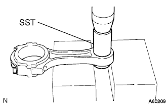
Using SST and a press, press out the bush.
- SST
- 09222-76012
-
-
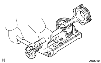
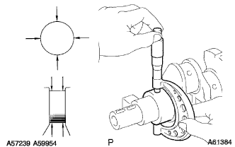
INSPECT CONNECTING ROD BOLT
-
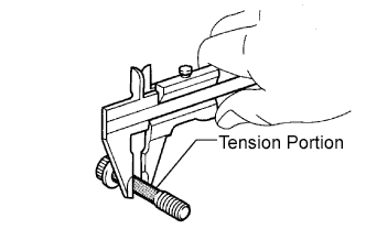
Using vernier calipers, measure the diameter of the tension portion of the connecting rod bolt.
Standard diameter 8.500 to 8.600 mm (0.3346 to 0.3385 in.) Minimum diameter 8.30 mm (0.3268 in.) If the diameter is less than the minimum, replace the bolt.
-
-
INSPECT CRANKSHAFT
-
Inspect for circle runout.
-
Place the crankshaft on V-blocks.
-
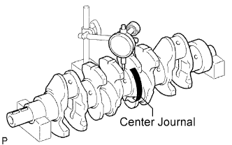
Using a dial indicator, measure the circle runout at the center journal.
Maximum circle runout 0.06 mm (0.0024 in.) If the circle runout is greater than the maximum, replace the crankshaft.
-
-
Inspect the main journals and crank pins.
-
Using a micrometer, measure the diameter of each main journal and crank pin.
Main journal diameter Size Diameter STD 69.982 to 70.000 mm (2.7552 to 2.7559 in.) U/S 0.25 69.745 to 69.755 mm (2.7459 to 2.7463 in.) U/S 0.50 69.495 to 69.505 mm (2.7360 to 2.7364 in.) Crank pin diameter Size Diameter STD 58.982 to 59.000 mm (2.3221 to 2.3228 in.) U/S 0.25 58.745 to 58.755 mm (2.3128 to 2.3132 in.) U/S 0.50 58.495 to 58.505 mm (2.3029 to 2.3033 in.) If the diameter is not as specified, check the oil clearance (see steps 68 and 74). If necessary, grind or replace the crankshaft.
-
Check each main journal and crank pin for taper and out-of-round as shown.
Maximum taper and out-of-round 0.02 mm (0.0008 in.) If the taper and out-of-round is greater than the maximum, replace the crankshaft.
-
-
If necessary, grind and hone the main journals and/or crank pins.
-
Grind and hone the main journals and/or crank pins to the finished undersized diameter (see procedure (b) above).
-
Install new main journal and/or crankshaft pin undersized bearing.
-
-
-
INSPECT CRANKSHAFT BEARING CAP BOLT
-
Using vernier calipers, measure the minimum diameter of the compressed thread at the measuring point (A).
Standard diameter 13.500 to 14.000 mm (0.5315 to 0.5512 in.) Minimum diameter 12.60 mm (0.4961 in.) If the diameter is less than the minimum, replace the bolt
-