ENGINE UNIT DISASSEMBLY

Note
-
When replacing the injectors (including shuffling the injectors between the cylinders), common rail or cylinder head, it is necessary to replace the injection pipes with new ones.
-
When replacing the fuel supply pump, common rail, cylinder block, cylinder head, cylinder head gasket or timing gear case, it is necessary to replace the fuel inlet pipe with a new one.
-
When replacing a fuel injector, check that the injection compensation codes of the fuel injectors installed on the cylinders match the ones registered in the ECM. If they do not match, correct the registered data (w/DPF: Click here, w/o DPF: Click here.
-
REMOVE OIL FILLER CAP SUB-ASSEMBLY
-
REMOVE NOZZLE HOLDER SEAL
-
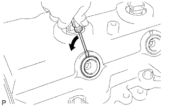
Using a small screwdriver, remove the 4 nozzle holder seals by prying between the holder seal and the cutout part of the cylinder head cover.
-
-
REMOVE CYLINDER HEAD COVER SUB-ASSEMBLY
-
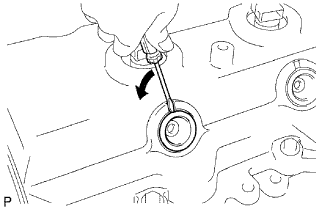
Using a small screwdriver, remove the nozzle holder seal by prying between the nozzle holder seal and the cutout part of the cylinder head cover.
-
Disconnect the ventilation hose.
-
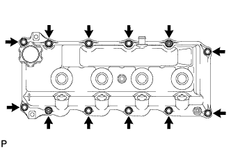
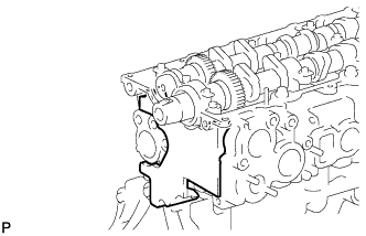
Remove the 10 bolts, 2 nuts, cylinder head cover and the cylinder head cover gasket.
-
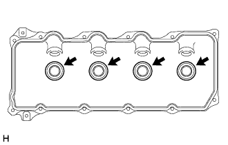
Remove the 4 No. 3 cylinder head cover gaskets from the cylinder head cover.
-
-
REMOVE INJECTOR ASSEMBLY
-
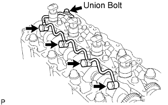
Remove the union bolt, 4 injector hollow screws, 5 gaskets and nozzle leakage pipe.
Note
-
When removing the nozzle leakage pipe, place a cushion under the pipe.
-
Be careful not to deform or scratch the union seal surface.
-
After removing the fuel pipe, put it in a plastic bag to prevent foreign matter from contaminating its injector inlet.
-
-
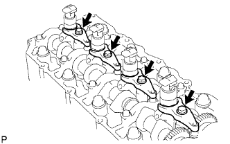
Remove the 4 bolts, 4 washers, 4 No. 1 nozzle holder clamps and 4 injectors.
Tech Tips
Arrange the injectors, No. 1 nozzle holder clamps, washers and bolts in the correct order.
-
Remove the O-ring from each injector.
-
Remove the 4 injection nozzle seats from the cylinder head.
-
-
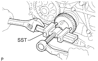
REMOVE CAMSHAFT TIMING PULLEY
-
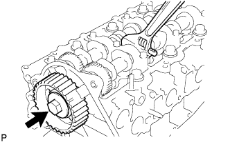
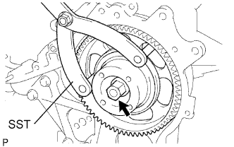
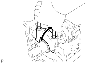
Remove the bolt of the camshaft timing pulley while holding the camshaft with a wrench.
-
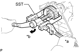
Text in Illustration *a Hold *b Turn Using SST, remove the camshaft timing pulley and key.
- SST
- 09950-40011 ( 09951-04010, 09952-04010, 09953-05010, 09957-04010 )
- 09955-04150
-
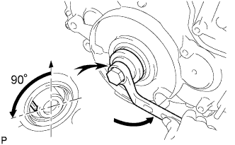
Rotate the crankshaft approximately 90° counterclockwise from TDC to lower the piston.
-
-
REMOVE NO. 2 TIMING BELT COVER
-
Remove the nut, 4 bolts and No. 2 timing belt cover.
-
-
REMOVE CYLINDER BLOCK INSULATOR
-
Remove the cylinder block insulator from the cylinder head.
-
-
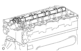
REMOVE NO. 2 CAMSHAFT
-
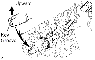
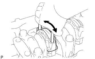
Position the key groove of the camshaft upward by turning the camshaft with a wrench.
-
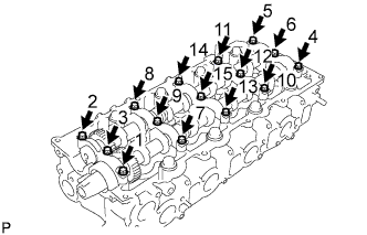
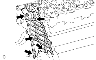
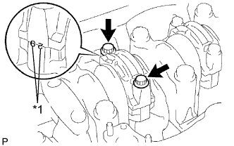
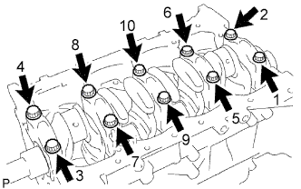
Uniformly loosen the 15 bearing cap bolts in several steps in the sequence shown in the illustration and remove the bolts.
-
Remove the 5 bearing caps.
-
Remove the No. 2 camshaft.
-
-
REMOVE CAMSHAFT
-
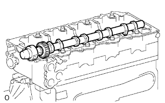
Remove the camshaft.
-
-
REMOVE CAMSHAFT SETTING OIL SEAL
-
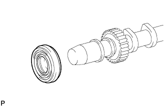
Remove the oil seal from the camshaft.
-
-
REMOVE CYLINDER HEAD SUB-ASSEMBLY
-
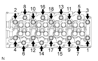
Uniformly loosen the 18 cylinder head bolts in several passes in the sequence shown in the illustration. Then remove the 18 cylinder head bolts and 18 washers.
Note
Head warpage or cracking could result from removing the bolts in an incorrect order.
-
Lift the cylinder head from the dowels on the cylinder block and place the cylinder head on wooden blocks on a workbench.
Note
Be careful not to damage the contact surfaces of the cylinder head or cylinder block.
Tech Tips
If the cylinder head is difficult to lift, use a screwdriver to pry between the cylinder head and block.
-
-
REMOVE CYLINDER HEAD GASKET
-
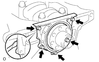
REMOVE WATER PUMP ASSEMBLY
-
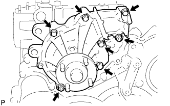
Remove the 5 bolts, 2 nuts, water pump and gasket.
-
-
REMOVE TIMING GEAR COVER
-
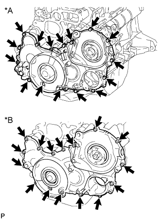
Text in Illustration *A w/ DPF *B w/o DPF Remove the 14 bolts and 2 nuts.
-
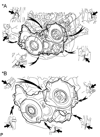
Text in Illustration *A w/ DPF *B w/o DPF Pry the timing gear cover at the locations shown in the illustration and remove the timing gear cover.
Note
Be careful not to drop the injection gear.
-
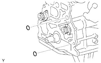
w/ DPF:
Remove the 3 O-rings from the timing gear case.
-
w/o DPF:
Remove the O-rings from the timing gear case.
-
-
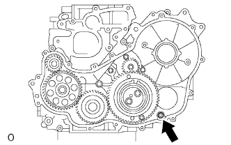
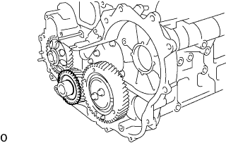
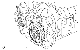
REMOVE INJECTION GEAR
-
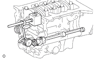
Secure the No. 2 idle sub gear to the No. 1 idle gear with a service bolt.
- Torque:
- 8.0 N*m { 82 kgf*cm, 71 in.*lbf }
Note
If the bolt hole of the No. 2 idle sub gear is not aligned with the bolt hole of the No. 1 idle gear, rotate the crankshaft counterclockwise to align the bolt holes. Then install the service bolt.
-
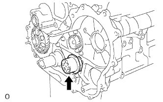
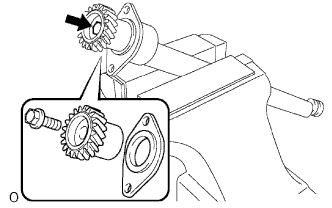
Remove the injection gear.
-
-
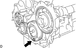
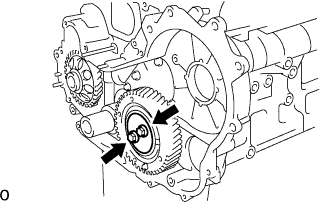
REMOVE NO. 1 CRANKSHAFT POSITION SENSOR PLATE
-
Remove the No. 1 crankshaft position sensor plate.
-
-
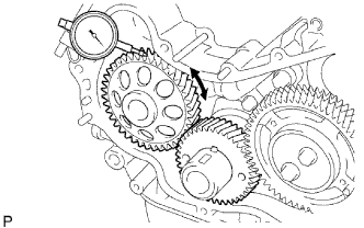
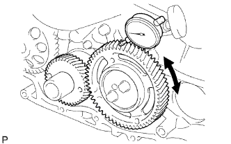
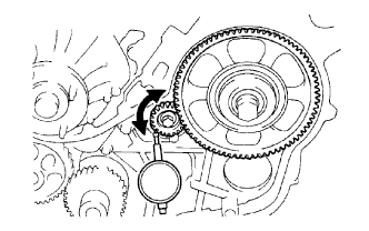
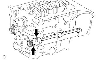
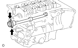
INSPECT BACKLASH OF OIL PUMP GEAR TO CRANKSHAFT TIMING GEAR
-
Using a dial indicator, measure the backlash.
Standard gear backlash 0.02 to 0.15 mm (0.0008 to 0.0060 in.) Maximum gear backlash 0.20 mm (0.0079 in.) If the gear backlash is more than the maximum, replace the gears as a set.
-
-
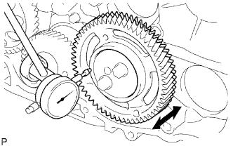
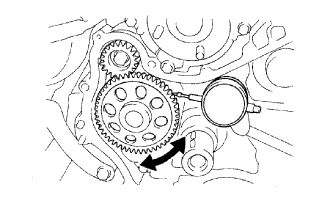
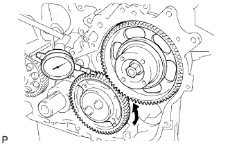
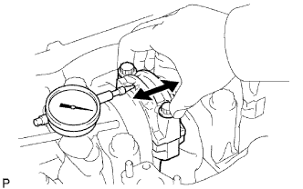
INSPECT NO. 1 IDLE GEAR THRUST CLEARANCE
-
Using a dial indicator, measure the thrust clearance.
Standard thrust clearance 0.06 to 0.11 mm (0.0024 to 0.0043 in.) Maximum thrust clearance 0.30 mm (0.0118 in.) If the thrust clearance is more than the maximum, replace the idle gear thrust plate. If necessary, replace the No. 1 idle gear and/or No. 1 idle gear shaft.
-
-
REMOVE IDLE GEAR THRUST PLATE
-
Remove the 2 bolts and idle gear thrust plate.
-
-
REMOVE NO. 1 IDLE GEAR
-
Remove the No. 1 idle gear together with the No. 1 and No. 2 idle sub gears.
-
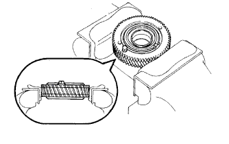
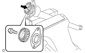
Mount the No. 1 idle gear and No. 2 idle sub gear in a vise.
Note
Be careful not to damage the gears.
-
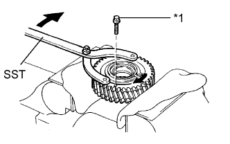
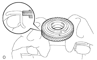
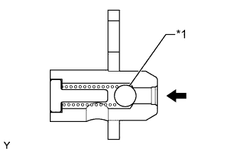
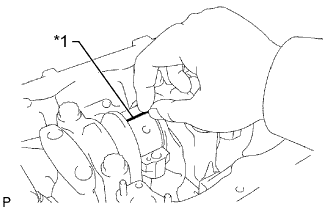
Text in Illustration *1 Service Bolt Using SST, turn the No. 1 idle sub gear clockwise and remove the service bolt.
- SST
- 09960-10010 ( 09962-01000, 09963-00600 )
-
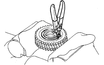
Using snap ring pliers, remove the shaft snap ring.
-
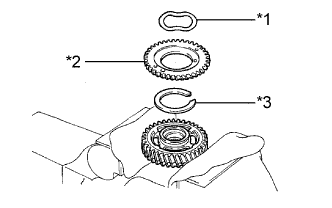
Text in Illustration *1 Wave Washer *2 No. 1 Idle Sub Gear *3 Idle Gear Spring Remove the wave washer, No. 1 idle sub gear and idle gear spring.
-
Remove the No. 1 idle gear and set it in a vise.
Note
Be careful not to damage the gear.
-
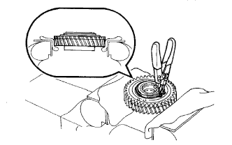
Using snap ring pliers, remove the shaft snap ring.
-
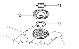
Text in Illustration *1 Wave Washer *2 No. 2 Idle Sub Gear *3 Idle Gear Spring Remove the wave washer, No. 2 idle sub gear and idle gear spring.
-
-
REMOVE NO. 1 IDLE GEAR SHAFT
-
Remove the No. 1 idle gear shaft.
-
-
INSPECT BACKLASH OF CRANKSHAFT TIMING GEAR TO NO. 1 IDLE GEAR
-
Install the No. 1 idle gear.
-
Using a dial indicator, measure the backlash.
Standard gear backlash 0.02 to 0.15 mm (0.0008 to 0.0060 in.) Maximum gear backlash 0.20 mm (0.0079 in.) If the gear backlash is more than the maximum, replace the gears as a set.
-
Remove the No. 1 idle gear.
-
-
REMOVE CRANKSHAFT TIMING GEAR
-
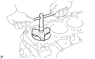
Using SST, remove the crankshaft timing gear.
- SST
- 09950-50013 ( 09951-05010, 09952-05010, 09953-05010, 09954-05021 )
-
-
INSPECT BACKLASH OF OIL PUMP GEAR TO NO. 1 BALANCESHAFT
-
Using a dial indicator, measure the backlash.
Standard gear backlash 0.02 to 0.15 mm (0.0008 to 0.0060 in.) Maximum gear backlash 0.20 mm (0.0079 in.) If the gear backlash is more than the maximum, replace the gears as a set.
-
-
INSPECT BACKLASH OF INJECTION GEAR TO NO. 2 BALANCESHAFT
-
Install the fuel supply pump with the 2 nuts.
- Torque:
- 21 N*m { 214 kgf*cm, 15 ft.*lbf }
-
Using SST, install the injection gear with the nut.
- Torque:
- 64 N*m { 650 kgf*cm, 47 ft.*lbf }
- SST
- 09960-10010 ( 09962-01000, 09963-01000 )
-
Using a dial indicator, measure the backlash.
Standard gear backlash 0.02 to 0.15 mm (0.0008 to 0.0060 in.) Maximum gear backlash 0.20 mm (0.0079 in.) If the gear backlash is more than the maximum, replace the gears as a set.
-
-
INSPECT BACKLASH OF INJECTION GEAR TO NO. 1 IDLE GEAR
-
Install the No. 1 idle gear without the sub gears.
-
Using a dial indicator, measure the backlash.
Standard gear backlash 0.02 to 0.15 mm (0.0008 to 0.0060 in.) Maximum gear backlash 0.20 mm (0.0079 in.) If the gear backlash is more than the maximum, replace the gears as a set.
-
Using SST, remove the nut and injection gear.
- SST
- 09960-10010 ( 09962-01000, 09963-01000 )
-
Remove the 2 nuts and fuel supply pump.
-
Remove the No. 1 idle gear.
-
-
REMOVE OIL CHECK VALVE SUB-ASSEMBLY (w/ DPF)
-
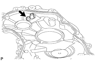
Using a 6 mm hexagon wrench, remove the bolt and oil check valve from the timing gear cover.
-
-
INSPECT OIL CHECK VALVE SUB-ASSEMBLY (w/ DPF)
-
Text in Illustration *1 Ball Push the ball of the oil check valve to check if it is stuck.
If the oil check valve is stuck, replace the oil check valve sub-assembly.
-
-
REMOVE ENGINE OIL LEVEL SENSOR
-
Remove the 4 bolts and engine oil level sensor.
-
-
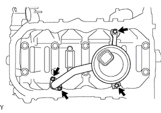
REMOVE OIL PAN SUB-ASSEMBLY
-
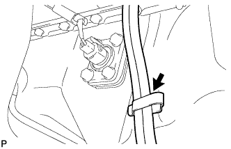
Disconnect the vinyl tube from the oil pan.
-
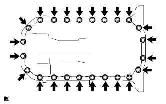
Remove the 22 bolts and 2 nuts.
-
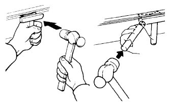
w/ DPF:
Insert the blade of an oil pan seal cutter between the oil pan and cylinder block, cut through the applied sealer, and then remove the oil pan.
Note
-
Do not use the oil pan seal cutter for the area between the oil pan and timing gear case, or for the area between the oil pan and rear oil seal retainer.
-
Be careful not to damage the oil pan flange.
-
-
w/o DPF:
Insert the blade of an oil pan seal cutter between the oil pan and cylinder block stiffening plate, cut through the applied sealer, and then remove the oil pan and cylinder block stiffening plate.
Note
-
Do not use the oil pan seal cutter for the area between the oil pan and timing gear case, or for the area between the oil pan and rear oil seal retainer.
-
Be careful not to damage the oil pan flange.
-
-
-
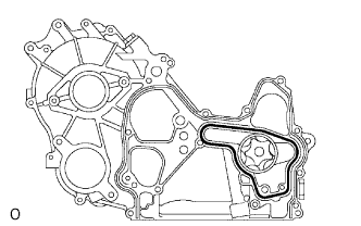
REMOVE OIL STRAINER SUB-ASSEMBLY
-
Remove the 2 bolts, 2 nuts, oil strainer and gasket.
-
-
REMOVE TIMING GEAR CASE ASSEMBLY
-
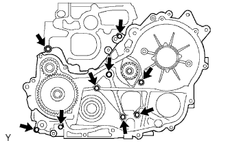
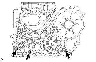
Remove the union bolt and 8 bolts.
-
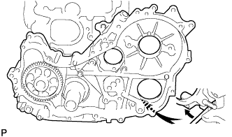
Pry the timing gear case at the location shown in the illustration and remove the timing gear case.
-
Remove the gasket.
-
Remove the 2 O-rings.
-
-
INSPECT NO. 1 BALANCESHAFT THRUST CLEARANCE
-
Using a dial indicator, measure the thrust clearance by moving the No. 1 balanceshaft back and forth.
Standard thrust clearance 0.065 to 0.140 mm (0.0026 to 0.0055 in.) Maximum thrust clearance 0.25 mm (0.0098 in.) If the thrust clearance is more than the maximum, replace the balanceshaft thrust washer. If the thrust clearance is still more than the maximum clearance, replace the No. 1 balanceshaft sub-assembly.
-
-
REMOVE NO. 1 BALANCESHAFT SUB-ASSEMBLY
-
Remove the 2 bolts and No. 1 balanceshaft.
-
-
REMOVE NO. 1 BALANCESHAFT DRIVEN GEAR
-
Mount the No. 1 balanceshaft between aluminum plates in a vise.
Note
Be careful not to damage the No. 1 balanceshaft.
-
Remove the bolt, No. 1 balanceshaft driven gear and balanceshaft thrust washer.
-
-
INSPECT NO. 2 BALANCESHAFT THRUST CLEARANCE
-

Using a dial indicator, measure the thrust clearance by moving the No. 2 balanceshaft back and forth.
Standard thrust clearance 0.065 to 0.140 mm (0.0026 to 0.0055 in.) Maximum thrust clearance 0.25 mm (0.0098 in.) If the thrust clearance is more than the maximum, replace the balanceshaft thrust washer. If the thrust clearance is still more than the maximum clearance, replace the No. 2 balanceshaft sub-assembly.
-
-
REMOVE NO. 2 BALANCESHAFT SUB-ASSEMBLY
-
Remove the 2 bolts and No. 2 balanceshaft.
-
-
REMOVE NO. 2 BALANCESHAFT DRIVEN GEAR
-
Mount the No. 2 balanceshaft between aluminum plates in a vise.
Note
Be careful not to damage the No. 2 balanceshaft.
-
Remove the bolt, No. 2 balanceshaft driven gear and balanceshaft thrust washer.
-
-
REMOVE REAR ENGINE OIL SEAL RETAINER
-
Remove the 5 bolts.
-
Using a screwdriver, remove the rear engine oil seal retainer by prying between the rear engine oil seal retainer and cylinder block.
-
-
REMOVE CYLINDER BLOCK OIL ORIFICE
-
INSPECT CONNECTING ROD THRUST CLEARANCE
-
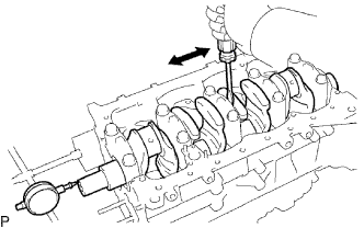
Using a dial indicator, measure the thrust clearance while moving the connecting rod back and forth.
Standard thrust clearance 0.100 to 0.300 mm (0.0039 to 0.0118 in.) Maximum thrust clearance 0.40 mm (0.0157 in.) If the thrust clearance is more than the maximum, replace the connecting rod sub-assembly. If necessary, replace the crankshaft.
-
-
REMOVE PISTON AND CONNECTING ROD
-
Text in Illustration *1 Matchmark Remove the 2 connecting rod cap bolts.
Tech Tips
Check the matchmarks on the connecting rod and cap to ensure correct reassembly.
-
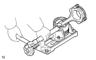
Using the 2 removed connecting rod bolts, pry the connecting rod cap back and forth and remove the connecting rod cap.
Tech Tips
Keep the lower bearing and connecting rod cap together.
-
Clean the crank pin and bearing.
-
Check the crank pin and bearings for pitting and scratches.
If the crank pin or a bearings is damaged, replace the bearings. If necessary, grind or replace the crankshaft.
-
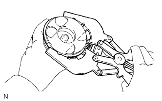
Using a ridge reamer, remove all carbon from the top of the cylinder.
-
Push the piston, connecting rod and upper bearing through the top of the cylinder block to remove them.
Tech Tips
-
Keep the bearings, connecting rod and cap together.
-
Be sure to organize the removed piston and connecting rod assemblies in such a way that they can be reinstalled exactly as before.
-
-
-
INSPECT CONNECTING ROD OIL CLEARANCE
-
Text in Illustration *1 Plastigage Lay a strip of Plastigage across the crank pin.
-
Text in Illustration *1 Matchmark Install the connecting rod cap with the 2 bolts.
Note
Do not turn the crankshaft.
Tech Tips
-
The connecting rod cap bolts are tightened in 2 progressive steps.
-
If any connecting rod bolt is broken or deformed, replace it.
-
Apply a light coat of engine oil to the threads and under the heads of the connecting rod cap bolts.
-
Install and alternately tighten the bolts of the connecting rod cap in several passes.
- Torque:
- 35 N*m { 357 kgf*cm, 26 ft.*lbf }
If any one of the connecting rod cap bolts does not meet the torque specification, replace the cap bolt.
-
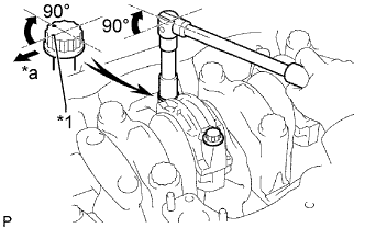
Text in Illustration *1 Paint Mark *a Front Mark the front of each of the connecting rod cap bolts with paint.
-
Tighten the connecting rod cap bolts by 90° as shown in the illustration.
-
Check that the paint marks are now at a 90° angle to the front.
-
-
Check the matchmarks on the connecting rod and cap to ensure correct reassembly.
-
Remove the 2 bolts, connecting rod cap and lower bearing.
-
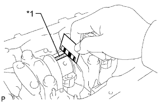
Text in Illustration *1 Plastigage 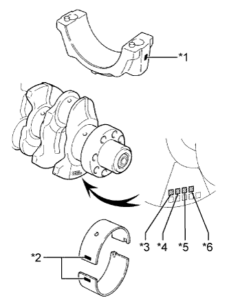
Text in Illustration *1 Mark 1, 2 or 3 *2 Mark 2, 3, 4, 5 or 6 *3 No. 1 *4 No. 2 *5 No. 3 *6 No. 4 Measure the Plastigage at its widest point.
Standard oil clearance 0.036 to 0.054 mm (0.0014 to 0.0021 in.) Maximum oil clearance 0.10 mm (0.0039 in.) If the oil clearance is more than the maximum, replace the bearings. If necessary, grind or replace the crankshaft.
Tech Tips
If using a standard bearing, replace it with one that has the same number. If the number of the bearing cannot be determined, select the correct bearing by adding together the numbers imprinted on the crankshaft and connecting rod, and then selecting the bearing with the same number as the total. There are 5 sizes of standard bearings, marked 2, 3, 4, 5 and 6.
Bearing Size Item Number Mark Connecting rod cap 1 2 3 Crankshaft 1 2 3 1 2 3 1 2 3 Bearing to be used 2 3 4 3 4 5 4 5 6 EXAMPLE:
Connecting rod cap "2" + Crankshaft "3" =
Total number 5 (Use bearing "5")
Reference Standard Connecting Rod Big End Inside Diameter Item Specified Condition Mark 1 62.014 to 62.020 mm (2.4415 to 2.4417 in.) Mark 2 62.020 to 62.026 mm (2.4417 to 2.4420 in.) Mark 3 62.026 to 62.032 mm (2.4420 to 2.4422 in.) Standard Crank Pin Diameter Item Specified Condition Mark 1 58.994 to 59.000 mm (2.3226 to 2.3228 in.) Mark 2 58.988 to 58.994 mm (2.3224 to 2.3226 in.) Mark 3 58.982 to 58.988 mm (2.3221 to 2.3224 in.) Standard Sized Connecting Rod Bearing Center Wall Thickness Item Specified Condition Mark 2 1.486 to 1.489 mm (0.0585 to 0.0586 in.) Mark 3 1.489 to 1.492 mm (0.0586 to 0.0587 in.) Mark 4 1.492 to 1.495 mm (0.0587 to 0.0589 in.) Mark 5 1.495 to 1.498 mm (0.0589 to 0.0590 in.) Mark 6 1.498 to 1.501 mm (0.0590 to 0.0591 in.) -
Completely remove the Plastigage.
-
-
INSPECT CRANKSHAFT THRUST CLEARANCE
-
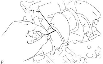
Using a dial indicator, measure the thrust clearance while prying the crankshaft back and forth with a screwdriver.
Standard thrust clearance 0.040 to 0.240 mm (0.0016 to 0.0094 in.) Maximum thrust clearance 0.30 mm (0.0118 in.) If the thrust clearance is more than the maximum, replace the thrust washers as a set.
Standard Thrust Washer Thickness Item Specified Condition STD 2.430 to 2.480 mm (0.0957 to 0.0976 in.) O/S 0.125 2.555 to 2.605 mm (0.1006 to 0.1026 in.) O/S 0.25 2.493 to 2.543 mm (0.0982 to 0.1001 in.)
-
-
INSPECT CRANKSHAFT OIL CLEARANCE
-
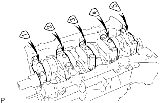
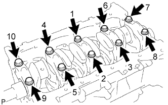
Uniformly loosen and remove the 10 crankshaft bearing cap bolts in several passes in the sequence shown in the illustration.
-
Using the removed crankshaft bearing cap bolts, pry the cap back and forth and remove the crankshaft bearing caps, lower crankshaft bearings and lower thrust washers (No. 5 crankshaft bearing cap only).
Tech Tips
-
Keep the lower bearing and crankshaft bearing cap together.
-
Be sure to organize the bearing caps and lower thrust washers (No. 5 crankshaft bearing only) in such a way that they can be reinstalled exactly as before.
-
-
Lift out the crankshaft.
-
Clean each main journal and bearing.
-
Check each crankshaft journal and bearing for pitting and scratches.
If a journal or bearing is damaged, replace the bearings. If necessary, grind or replace the crankshaft.
-
Place the crankshaft on the cylinder block.
-
Text in Illustration *1 Plastigage Lay a strip of Plastigage across each journal.
-
Place the 5 crankshaft bearing caps in their proper locations.
-
Install the 5 crankshaft bearing caps with the 10 bolts.
Note
Do not turn the crankshaft.
Tech Tips
-
The crankshaft bearing cap bolts are tightened in 2 progressive steps.
-
If a crankshaft bearing cap bolt is broken or deformed, replace it.
-
Apply a light coat of engine oil to the threads and under the bolt heads of the crankshaft bearing cap bolts.
-
Install and uniformly tighten the 10 bolts of the crankshaft bearing caps in several passes in the sequence shown in the illustration.
- Torque:
- 50 N*m { 510 kgf*cm, 37 ft.*lbf }
If any one of the bearing cap bolts does not meet the torque specification, replace the bearing cap bolt.
-
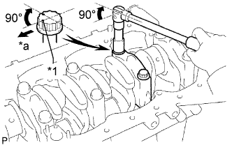
Text in Illustration *1 Paint Mark *a Front Mark the front of each crankshaft bearing cap bolt with paint.
-
Tighten the crankshaft bearing cap bolts by 90° in the numerical order shown in the previous illustration.
-
Check that the paint marks are now at a 90° angle to the front.
-
-
Remove the 10 bolts and 5 crankshaft bearing caps.
-
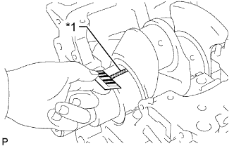
Text in Illustration *1 Plastigage 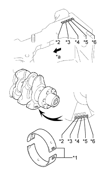
Text in Illustration *1 Mark 2, 3, 4, 5 or 6 *2 No. 1 *3 No. 2 *4 No. 3 *5 No. 4 *6 No. 5 *a Front Measure the Plastigage at its widest point.
Standard Oil Clearance Item Specified Condition STD 0.030 to 0.048 mm (0.0012 to 0.0019 in.) U/S 0.25, U/S 0.50 0.037 to 0.077 mm (0.0015 to 0.0030 in.) Maximum clearance 0.10 mm (0.0039 in.) If the oil clearance is more than the maximum, replace the bearings. If necessary, grind or replace the crankshaft.
Tech Tips
If replacing the cylinder block sub-assembly, the bearing oil clearance will be within the standard range.
Standard oil clearance 0.030 to 0.048 mm (0.0012 to 0.0019 in.) Tech Tips
If using a standard bearing, replace it with one that has the same number. If the number of the bearing cannot be determined, select the correct bearing by adding together the numbers imprinted on the cylinder block and crankshaft, and then selecting the bearing with the same number as the total. There are 5 sizes of standard bearings, marked 2, 3, 4, 5 and 6.
Bearing Size Item Number Mark Cylinder block 1 2 3 Crankshaft 1 2 3 1 2 3 1 2 3 Bearing to be used 2 3 4 3 4 5 4 5 6 EXAMPLE: Cylinder block "2" + Crankshaft "1"
= Total number 3 (Use bearing "3")
Reference Standard Cylinder Block Main Journal Bore Diameter Item Specified Condition Mark 1 75.000 to 75.006 mm (2.9528 to 2.9530 in.) Mark 2 75.006 to 75.012 mm (2.9530 to 2.9532 in.) Mark 3 75.012 to 75.018 mm (2.9532 to 2.9535 in.) Standard Crankshaft Journal Diameter Item Specified Condition Mark 1 69.994 to 70.000 mm (2.7557 to 2.7559 in.) Mark 2 69.988 to 69.994 mm (2.7554 to 2.7557 in.) Mark 3 69.982 to 69.988 mm (2.7552 to 2.7554 in.) Standard Sized Main Bearing Center Wall Thickness Item Specified Condition Mark 2 2.482 to 2.485 mm (0.0977 to 0.0978 in.) Mark 3 2.485 to 2.488 mm (0.0978 to 0.0980 in.) Mark 4 2.488 to 2.491 mm (0.0980 to 0.0981 in.) Mark 5 2.491 to 2.494 mm (0.0981 to 0.0982 in.) Mark 6 2.494 to 2.497 mm (0.0982 to 0.0983 in.) -
Completely remove the Plastigage.
-
-
REMOVE PISTON PIN
-
Check the fit between the piston and piston pin.
-
Try to move the piston back and forth on the piston pin.
If any movement is felt, replace the piston and pin as a set.
-
-
Using a piston ring expander, remove the 2 compression rings.
Tech Tips
Be sure to organize the removed piston rings in such a way that they can be reinstalled exactly as before.
-
Remove the oil ring by hand.
-
Disconnect the connecting rod from the piston.
-
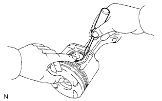
Using a small screwdriver, pry off the 2 snap rings from the piston.
-
Gradually heat the piston to approximately 80°C (176°F).
-
Using a plastic-faced hammer and brass bar, lightly tap out the piston pin. Then remove the connecting rod.
Tech Tips
-
The piston and pin are a matched set.
-
Be sure to organize the removed pistons, pins, rings, connecting rods and bearings in such a way that the parts can be reinstalled exactly as before.
-
-
-
-
REMOVE CRANKSHAFT
-
Uniformly loosen and remove the 10 crankshaft bearing cap bolts in several passes in the sequence shown in the illustration.
-
Using the removed crankshaft bearing cap bolts, pry the cap back and forth, and remove the crankshaft bearing caps, lower crankshaft bearings and lower thrust washers (No. 5 crankshaft bearing cap only).
Tech Tips
-
Keep the lower bearing and crankshaft bearing cap together.
-
Be sure to organize the bearing caps and lower thrust washers (No. 5 crankshaft bearing only) in such a way that they can be reinstalled exactly as before.
-
-
Lift out the crankshaft.
-
Remove the upper bearings and upper thrust washers from the cylinder block.
Tech Tips
Arrange the main bearing caps, bearings and thrust washers in the correct order.
-
-
REMOVE NO. 1 OIL NOZZLE SUB-ASSEMBLY
-
Remove the 4 check valves and 4 No. 1 oil nozzles.
-
-
REMOVE OIL FILTER BRACKET WITH HEAD STRAIGHT SCREW PLUG
Tech Tips
It is not necessary to remove the oil filter bracket with head straight screw plug unless it is being replaced.
-
Remove the oil filter bracket with head straight screw plug and the gasket.
-
-
REMOVE PLATE PLUG
Tech Tips
It is not necessary to remove the plate plug unless it is being replaced.
-
Remove the bolt, plate plug and O-ring.
-
-
REMOVE HOLE PLUG
Tech Tips
It is not necessary to remove the hole plug unless it is being replaced.
-
Remove the bolt, hole plug and O-ring.
-
-
REMOVE RING PIN
Tech Tips
It is not necessary to remove a ring pin unless it is being replaced.
-
Text in Illustration *a Cylinder Head Side Remove the 2 ring pins shown in the illustration.
-
-
REMOVE STRAIGHT PIN
Tech Tips
It is not necessary to remove a straight pin unless it is being replaced.
-
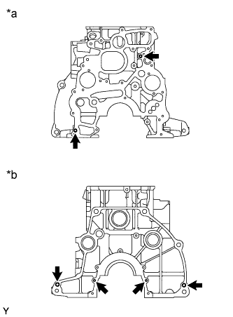
Text in Illustration *a Front Side *b Rear Side Remove the 6 straight pins shown in the illustration.
-
-
REMOVE STUD BOLT
Tech Tips
If a stud bolt is deformed or its threads are damaged, replace it.
-
Remove the 11 stud bolts shown in the illustration.
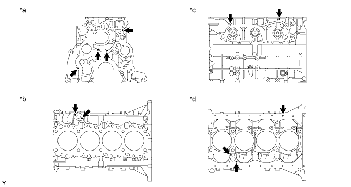
Text in Illustration *a Front Side *b Upper Side *c Left Side *d Lower Side
-
-
REMOVE TIGHT PLUG
Tech Tips
If coolant leaks from a tight plug or a plug is corroded, replace it.
-
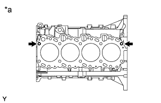
Remove the 13 tight plugs shown in the illustration.
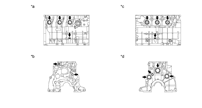
Text in Illustration *a Right Side *b Front Side *c Left Side *d Rear Side
-