ENGINE ASSEMBLY INSTALLATION

-
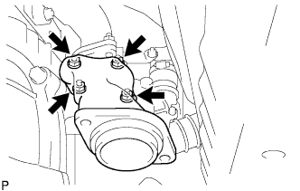
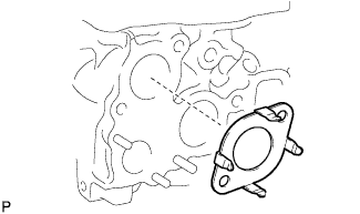
INSTALL ENGINE OIL LEVEL SENSOR
-
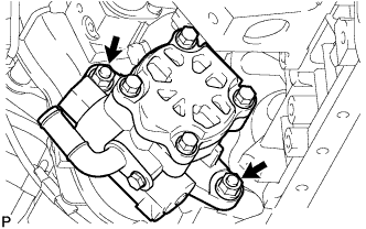
Set a new gasket, and then install the engine oil level sensor with the 4 bolts.
- Torque:
- 7.0 N*m { 71 kgf*cm, 52 in.*lbf }
-
-
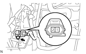
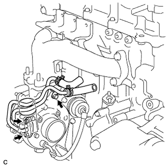
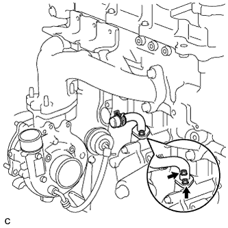
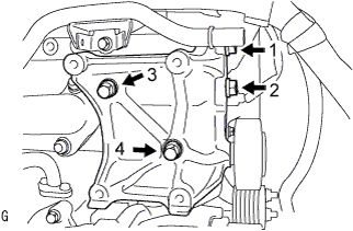
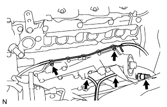
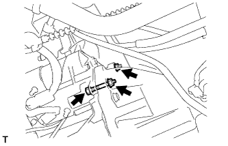
INSTALL CRANKSHAFT POSITION SENSOR
-
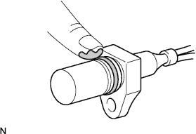
Apply a light coat of engine oil to the O-ring of the crankshaft position sensor.
-
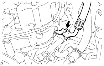
Install the crankshaft position sensor with the bolt.
- Torque:
- 8.5 N*m { 87 kgf*cm, 75 in.*lbf }
Note
Be careful that the O-ring is not cracked or jammed when installing the crankshaft position sensor.
-
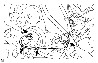
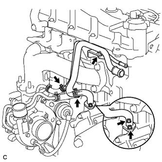
Connect the 3 wire harness clamps.
-
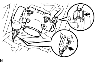
Connect the crankshaft position sensor connector to the vacuum pipe No.1.
-
Connect the crankshaft position sensor connector.
-
-
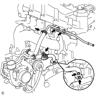
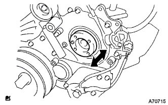
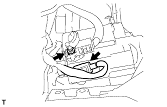
INSTALL CAMSHAFT POSITION SENSOR
-
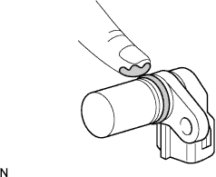
Apply a light coat of engine oil to the O-ring of the camshaft position sensor.
-
Install the camshaft position sensor with the bolt.
- Torque:
- 8.5 N*m { 87 kgf*cm, 75 in.*lbf }
Note
Be careful that the O-ring is not cracked or jammed when installing the camshaft position sensor.
-
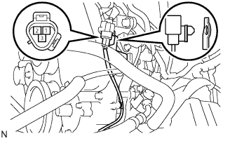
Connect the camshaft position sensor connector.
-
-
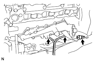
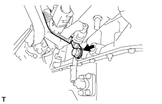
INSTALL DIESEL ENGINE WATER TEMPERATURE SENSOR
-
Using a deep-socket wrench (17 mm), install the water temperature sensor.
- Torque:
- 20 N*m { 204 kgf*cm, 15 ft.*lbf }
-
-
INSTALL VACUUM PUMP ASSEMBLY
-
INSTALL CRANKSHAFT PULLEY
-
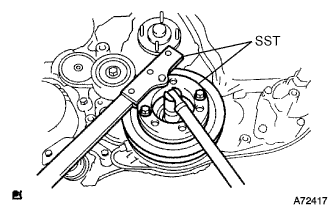
Tighten the bolt holding the crankshaft pulley with SST.
- SST
- 09213-58013
- 09330-00021
- Torque:
- 365 N*m { 3,722 kgf*cm, 270 ft.*lbf }
-
-
INSTALL TIMING BELT IDLER SUB-ASSEMBLY NO.1
-
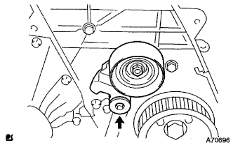
Using a 10 mm hexagon wrench, install a new washer and the timing belt idler with the bolt.
- Torque:
- 35 N*m { 357 kgf*cm, 26 ft.*lbf }
Note
Do not reuse the washer.
-
-
INSTALL ENGINE MOUNTING BRACKET FRONT NO.1 RH
-
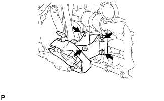
Install the engine mounting bracket front No.1 RH with the 4 bolts.
- Torque:
- 68 N*m { 693 kgf*cm, 50 ft.*lbf }
-
-
INSTALL EXHAUST MANIFOLD
-
Install a new gasket and the exhaust manifold with the 2 bolts and 6 nuts.
- Torque:
- 52 N*m { 530 kgf*cm, 38 ft.*lbf }
-
-
INSTALL TURBOCHARGER SUB-ASSEMBLY
-
INSTALL TURBINE OUTLET ELBOW
-
Install a new gasket to the turbocharger.
-
Install the turbine outlet elbow with 4 new bolts.
- Torque:
- 26 N*m { 260 kgf*cm, 19 ft.*lbf }
-
-
INSTALL TURBO WATER PIPE SUB-ASSEMBLY NO.2 (for Water Cooled Turbocharger)
-
Install a new gasket onto the turbocharger.
-
Install the turbo water pipe No.2 with the bolt and 2 nuts to the turbocharger.
- Torque:
- Bolt
- 12 N*m { 122 kgf*cm, 9 ft.*lbf }
- Nut
- 8.0 N*m { 82 kgf*cm, 71 in.*lbf }
-
-
INSTALL WATER BY-PASS PIPE SUB-ASSEMBLY NO.2
-
Water cooled turbocharger (w/ heater)
-
Install a new gasket onto the cylinder block.
-
Install the water by-pass pipe No.2 with the bolt and 2 nuts.
- Torque:
- Bolt
- 18 N*m { 184 kgf*cm, 13 ft.*lbf }
- Nut
- 8.0 N*m { 82 kgf*cm, 71 in.*lbf }
-
Connect the 2 water hoses with the 2 clips.
-
Connect the water by-pass hose No.3 with the clip.
-
Connect the heater water inlet hose with the clip.
-
-
Water cooled turbocharger (w/o heater)
-
Install a new gasket onto the cylinder block.
-
Install the water by-pass pipe No.2 with the 2 nuts.
- Torque:
- 8.0 N*m { 82 kgf*cm, 71 in.*lbf }
-
Install the turbo water pipe No.2 with the 2 bolts.
- Torque:
- 18 N*m { 184 kgf*cm, 13 ft.*lbf }
-
Connect the 2 water hoses with the 2 clips.
-
Connect the water by-pass hose No.3 with the clip.
-
-
Air cooled turbocharger (w/o heater)
-
Install a new gasket onto the cylinder block.
-
Install the water by-pass pipe No.2 with the 2 nuts.
- Torque:
- 8.0 N*m { 82 kgf*cm, 71 in.*lbf }
-
-
-
INSTALL COMPRESSOR ELBOW STAY
-
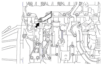
Install the compressor elbow stay with the bolt.
- Torque:
- 32 N*m { 326 kgf*cm, 23 ft.*lbf }
-
-
INSTALL VENTILATION HOSE HEAT INSULATOR
-
Install the ventilation hose insulator heat with the 2 bolts.
- Torque:
- 12 N*m { 122 kgf*cm, 9 ft.*lbf }
-
-
INSTALL VENTILATION PIPE
-
Install the ventilation pipe with the bolt.
- Torque:
- 20 N*m { 204 kgf*cm, 15 ft.*lbf }
-
-
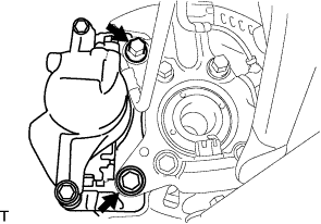
INSTALL V-RIBBED BELT TENSIONER ASSEMBLY
-
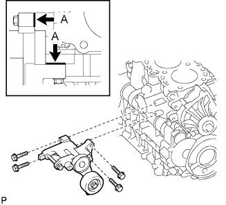
Temporarily install the V-ribbed belt tensioner with the 4 bolts.
Tech Tips
Make sure that the V-ribbed belt tensioner is in contact with the engine block at points A shown in the illustration.
-
Tighten the V-ribbed belt tensioner with the 4 bolts.
- Torque:
- 21 N*m { 214 kgf*cm, 15 ft.*lbf }
-
-
INSTALL GENERATOR ASSEMBLY
-
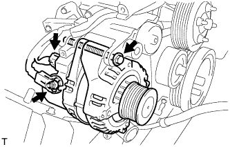
Install the generator assembly with the bolt.
- Torque:
- 62 N*m { 632 kgf*cm, 46 ft.*lbf }
-
Install the generator wire to terminal B with the nut.
- Torque:
- 9.8 N*m { 100 kgf*cm, 87 in.*lbf }
-
Install the terminal cap.
-
Connect the generator connector.
-
-
INSTALL GENERATOR BRACKET
-
Install the generator bracket with the bolt.
- Torque:
- 36 N*m { 367 kgf*cm, 27 ft.*lbf }
Note
Fully tighten the generator bracket after installing the generator assembly.
-
-
INSTALL IDLER PULLEY ASSEMBLY (w/ Air Conditioning System)
-
Install the idler pulley and washers with the bolt.
- Torque:
- 45 N*m { 459 kgf*cm, 33 ft.*lbf }
-
-
INSTALL COMPRESSOR BRACKET (w/ Air Conditioning System)
-
Temporarily install the compressor bracket with the 4 bolts.
Tech Tips
Make sure that the compressor bracket is in contact with the engine block.
-
Install the compressor bracket by tightening the 4 bolts as shown in the illustration.
- Torque:
- 45 N*m { 459 kgf*cm, 33 ft.*lbf }
-
-
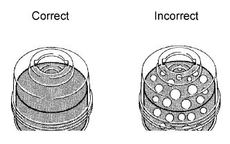
INSTALL THERMOSTAT
-
Install a new gasket to the thermostat.
-
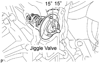
Install the thermostat with the jiggle valve facing up.
Tech Tips
The jiggle valve may be set within 15° on either side of the prescribed position.
-
-
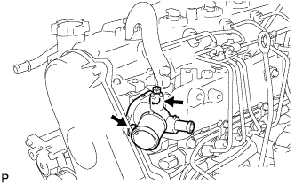
INSTALL WATER INLET
-
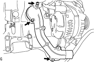
Install the water inlet with the 3 bolts.
- Torque:
- 13 N*m { 133 kgf*cm, 10 ft.*lbf }
-
-
INSTALL GLOW PLUG
-
Using a deep socket wrench (12 mm), install the 4 glow plugs.
- Torque:
- 13 N*m { 133 kgf*cm, 10 ft.*lbf }
-
-
INSTALL GLOW PLUG NO.1 CONNECTOR
-
Install the glow plug No.1 connectors with the 4 nuts.
- Torque:
- 2.2 N*m { 22 kgf*cm, 16 in.*lbf }
-
Install the 4 grommets.
-
-
INSTALL ENGINE MOUNTING BRACKET FRONT NO.1 LH
-
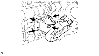
Install the engine mounting bracket front No.1 LH with the 4 bolt.
- Torque:
- 68 N*m { 693 kgf*cm, 50 ft.*lbf }
-
-
INSTALL WATER OUTLET
-
Set a new gasket.
-
Install the water outlet with the 2 bolts.
- Torque:
- 19 N*m { 194 kgf*cm, 14 ft.*lbf }
-
-
INSTALL OIL COOLER COVER SUB-ASSEMBLY (w/o EGR Valve)
-
Install a new gasket and oil cooler cover with the 2 nuts and 13 bolts.
- Torque:
- 13 N*m { 133 kgf*cm, 10 ft.*lbf }
-
Install the oil drain hoses.
-
Connect the oil pressure switch connector.
-
-
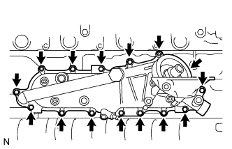
INSTALL OIL COOLER COVER SUB-ASSEMBLY (w/ EGR Valve)
-
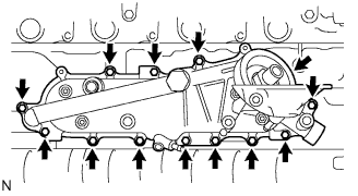
Install a new gasket and oil cooler cover with the 13 bolts.
- Torque:
- 13 N*m { 133 kgf*cm, 10 ft.*lbf }
-
Install the vacuum transmitting pipe No.2 with the 2 nuts.
- Torque:
- 13 N*m { 133 kgf*cm, 10 ft.*lbf }
-
Install the oil drain hoses.
-
Connect the oil pressure switch connector.
-
-
INSTALL INJECTION OR SUPPLY PUMP ASSEMBLY
-
Confirm that the supply pump gear in the timing gear case moves back and forth smoothly.
-
Install a new O-ring and the pulley key to the supply pump.
-
Aligning the projecting edge of the supply pump head to the key-slot of the supply pump gear, install the pump to the timing gear case.
-
While holding the supply pump by hand, push the supply pump gear rearward to engage the pump gear and drive shaft.
-
Temporarily install the supply pump with the 2 nuts.
-
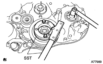
Using SST, hold the crankshaft.
- SST
- 09213-58013
- 09330-00021
-
Install the supply pump gear set nut.
Tech Tips
Set a new O-ring before tightening the supply pump gear set nut.
- Torque:
- 64 N*m { 653 kgf*cm, 47 ft.*lbf }
-
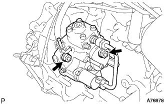
Temporarily install the supply pump stay with the 2 bolts on the engine block side.
-
Tighten the 2 nuts for the injection pump.
- Torque:
- 21 N*m { 214 kgf*cm, 16 ft.*lbf }
-
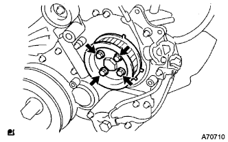
Install the camshaft timing pulley flange No.2 and pump drive shaft pulley with the 4 bolts.
- Torque:
- 31 N*m { 316 kgf*cm, 23 ft.*lbf }
-
-
CHECK PUMP DRIVE SHAFT THRUST CLEARANCE
-
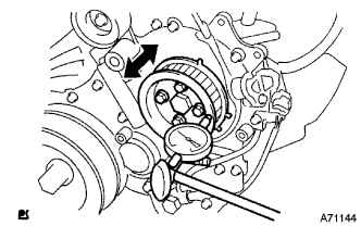
Push the pump drive shaft pulley back and forth to check a thrust clearance of the injection pump drive shaft.
Thrust clearance 0.15 to 0.55 mm (0.0059 to 0.0217 in.) Note
Make sure that the crankshaft pulley's notch is at 30 degree in the counterclockwise direction form the TDC position.
Tech Tips
If there is not thrust clearance, disassemble and reassemble the injection pump and pump drive shaft pulley.
-
-
INSTALL COMMON RAIL ASSEMBLY
-
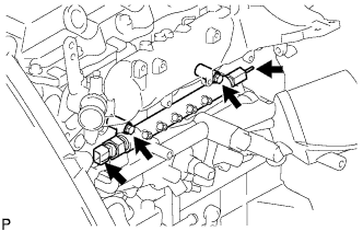
Install the common rail assembly with the 2 bolts.
- Torque:
- 38 N*m { 387 kgf*cm, 28 ft.*lbf }
-
Connect the fuel hose to the fuel pressure limiter.
-
Connect the fuel pressure sensor connector.
-
-
INSTALL OIL FILTER SUB-ASSEMBLY
-
Apply clean engine oil to the gasket of a new oil filter.
Note
Check and clean the oil filter installation surface.
-
Lightly screw the oil filter into place by hand. Tighten it until the gasket contacts the seat.
-
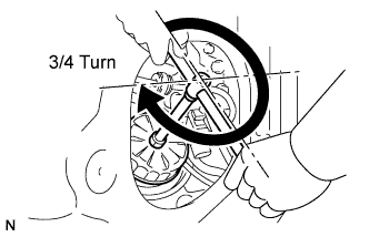
Using SST, tighten the oil filter until the gasket contacts the seat, and then turn it further 3/4.
- SST
- 09228-07501
-
-
INSTALL INTAKE MANIFOLD
-
Install a new gasket and the intake manifold with the 4 bolts and 2 nuts.
- Torque:
- 29 N*m { 296 kgf*cm, 21 ft.*lbf }
-
Install the manifold stay with the bolt and nut.
- Torque:
- 19 N*m { 194 kgf*cm, 14 ft.*lbf }
-
Connect the ground cable with the bolt.
-
-
INSTALL NOZZLE LEAKAGE PIPE ASSEMBLY NO.2
-
Temporarily install the nozzle leakage pipe with the 2 bolts.
-
Install the new gasket and union bolt to the nozzle leakage pipe.
- Torque:
- 21 N*m { 214 kgf*cm, 15 ft.*lbf }
-
Tighten the 2 bolts.
- Torque:
- 13 N*m { 133 kgf*cm, 10 ft.*lbf }
-
-
INSTALL FUEL INLET PIPE SUB-ASSEMBLY
Note
-
When replacing the fuel supply pump, common rail, cylinder block, cylinder head, cylinder head gasket, or timing gear case with a new one, replace the fuel inlet pipe.
-
Be careful not to adhere dusts, dirt or any other materials onto the joint area of the fuel inlet pipe.
-
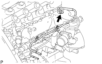
Temporarily install the fuel inlet pipe.
-
Using SST, tighten the injection pipe on the common rail side.
- SST
- 09023-12701
- Torque:
- 32 N*m { 326 kgf*cm, 24 ft.*lbf, for use with SST }
-
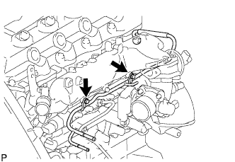
Using SST, tighten the injection pipe on the supply pump side.
- SST
- 09023-12701
- Torque:
- 32 N*m { 326 kgf*cm, 24 ft.*lbf, for use with SST }
-
-
INSTALL INJECTION PIPE
- SST
- 09023-12701
Note
-
When replacing the fuel injector, common rail, or cylinder head with a new one, replace injection pipes No. 1, No. 2, No. 3, and No. 4.
-
Keep clean the joint of the injection pipe.
-
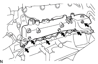
Install the injection pipes.
-
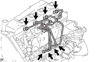
Temporarily install the 4 injection pipes.
-
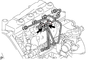
Install the injection pipe clamp No.3 in 2 nuts.
- Torque:
- 5.0 N*m { 51 kgf*cm, 44 in.*lbf }
-
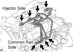
Fasten the union sequentially, from the injection pipe common rail to the injector, using SST.
- SST
- 09023-12701
- Torque:
- Use union nut wrench and torque wrench
- 32 N*m { 326 kgf*cm, 24 ft.*lbf }
-
-
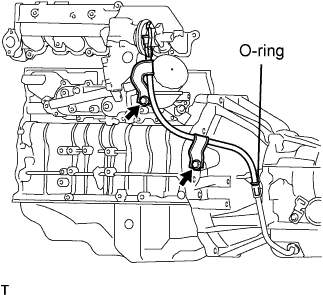
INSTALL OIL LEVEL GAUGE GUIDE
-
Install a new O-ring to the oil level gauge guide.
-
Apply a light coat of engine oil to the O-ring.
-
Install the oil level gauge guide with the bolt.
- Torque:
- 8.0 N*m { 82 kgf*cm, 71 in.*lbf }
-
Install the oil level gauge.
-
-
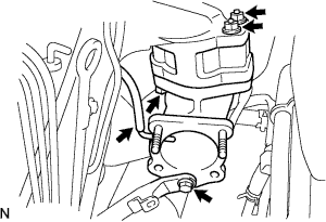
INSTALL ELECTRIC EGR CONTROL VALVE ASSEMBLY (w/ EGR Valve)
-
Temporarily tighten the EGR valve assembly with the sensor.
-
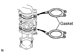
Install 2 new gaskets and the EGR valve to the intake air connector as shown in the illustration.
-
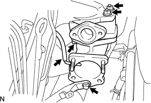
Temporarily tighten the intake air connector with EGR valve assembly to the intake manifold with the bolt and the 2 nuts.
-
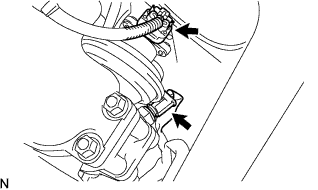
Install the vacuum hose to the intake air connector.
-
Temporarily tighten the manifold stay with the bolt.
-
Connect the EGR valve position sensor connector.
-
Connect the intake air temperature sensor connector.
-
-
Install the vacuum regulating valve.
-

Install the vacuum regulating valve with the 2 bolts.
- Torque:
- 20 N*m { 204 kgf*cm, 15 ft.*lbf }
-
Connect the 2 vacuum hoses and the regulating valve connector.
-
-
-
INSTALL INTAKE AIR CONNECTOR (w/o EGR Valve)
-
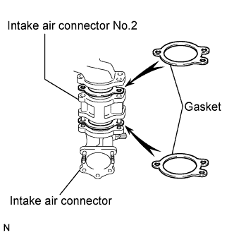
Temporarily install 2 new gaskets and intake air connector No.2 to the intake air connector.
-
Temporarily tighten the intake air connector assembly with the bolt and 2 nuts.
-
Tighten the manifold stay with the bolt.
-
Tighten the intake air connector with the bolt and 2 nuts.
-
Install the vacuum hose to the intake air connector.
-
-
INSTALL EGR PIPE SUB-ASSEMBLY NO.1 (w/ EGR Valve)
-
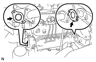
Install 2 new gaskets to the cylinder head and the EGR pipe sub-assembly No.1 as shown in the illustration.
-
Install the EGR pipe with the 2 bolts and the 2 nuts.
- Torque:
- 13 N*m { 133 kgf*cm, 10 ft.*lbf }
-
Connect the fuel pressure sensor connector.
-
-
INSTALL DIESEL THROTTLE BODY ASSEMBLY
Note
After removing and installing, or replacing the throttle body, be sure to perform the operation check.
-
Install a new gasket to intake air connector.
-
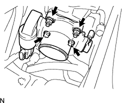
Install the throttle body with the 2 bolts and the 2 nuts.
- Torque:
- 20 N*m { 204 kgf*cm, 15 ft.*lbf }
-
Connect the 2 throttle body connectors.
-
-
INSTALL FAN PULLEY
-
Install the fan pulley with the 4 nuts.
- Torque:
- 23 N*m { 235 kgf*cm, 17 ft.*lbf }
-
-
PERFORM PISTON AND VALVE BREAK PREVENT WORK
-
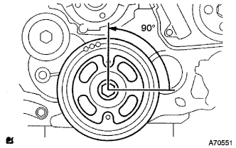
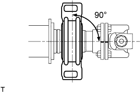
When turning the camshaft with the timing belt removed, turn the crankshaft 90° counterclockwise.
Note
When installing the timing belt, it is necessary to return the camshaft to the timing marks and then turn the crankshaft clockwise so that it aligns with the timing marks as shown in the illustration.
-
-
INSTALL TIMING BELT
-
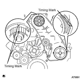
Check that the timing marks are aligned as shown in the illustration.
-
Install the timing belt to pump drive shaft pulley, camshaft timing pulley and timing belt idler No.1 in sequence.
-
Set the tensioner to the press upright.
Note
-
Do not allow the rod end to scratch and deform.
-
Press the tensioner rod in upward.
-
Protect a tip of the push rod with a rag in order to prevent damage.
-
-
Using a press, slowly apply 981 to 9,807 N (100 to 1,000 kgf, 220 to 2,205 lbf) of force to the push rod.
Note
Do not apply loads 981 to 9,807 N (100 to 1,000 kgf, 220 to 2,205 lbf) or more on the push rod.
-
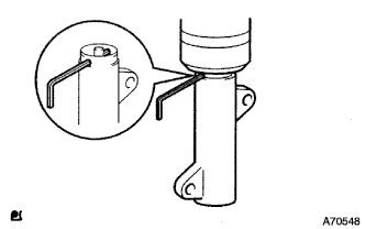
Align the holes of push rod and housing, pass a 1.27 mm hexagon wrench through the holes to keep the setting position of the push rod.
-
Temporarily install the timing belt tensioner with the 2 bolts while pushing the idler pulley toward the timing belt.
-
Tighten the 2 bolts.
- Torque:
- 13 N*m { 133 kgf*cm, 10 ft.*lbf }
Note
Uniformly tighten the 2 bolts and install the tensioner
-
Remove the 1.5 mm hexagon wrench from the tensioner.
-
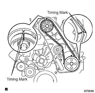
Turn the crankshaft in the clockwise direction twice, check that the timing marks are aligned as shown in the illustration.
-
-
INSTALL TIMING BELT COVER NO.1
-
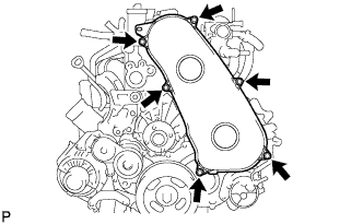
Install the timing belt No.1 cover with the 6 bolts.
- Torque:
- 6.0 N*m { 61 kgf*cm, 53 in.*lbf }
-
-
INSTALL VANE PUMP ASSEMBLY
-
Install a new vane pump O-ring to the vane pump assembly.
-
Install the vane pump assembly with the 2 nuts.
- Torque:
- 39 N*m { 398 kgf*cm, 29 ft.*lbf }
Note
Make sure that the vane pump O-ring is not caught between other parts.
-
-
REMOVE ENGINE STAND
-
INSTALL FRONT SUSPENSION CROSS MEMBER
-
Install the engine assembly to the cross member.
-
Install the 4 bolts for the left and right sides of the front suspension cross member.
- Torque:
- 55 N*m { 561 kgf*cm, 41 ft.*lbf }
-
-
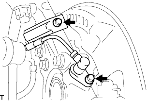
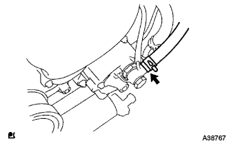
CONNECT PRESSURE FEED TUBE ASSEMBLY
-
Install a new gasket to the pressure feed tube assembly.
-
Connect the pressure feed tube assembly to the vane pump assembly with the union bolt.
- Torque:
- 50 N*m { 510 kgf*cm, 37 ft.*lbf }
Tech Tips
Make sure the stopper of the pressure feed tube assembly contacts the vane pump assembly as shown in the illustration.
-
-
CONNECT OIL RESERVOIR TO PUMP HOSE NO.1
-
Connect the oil reservoir to pump hose No.1 to the vane pump assembly with the clip.
-
-
INSTALL ENGINE WIRE
-
Install the engine wire to the engine assembly.
-
-
INSTALL REAR END PLATE
-
Install the rear end plate with the bolt.
- Torque:
- 8.0 N*m { 82 kgf*cm, 71 in.*lbf }
-
-
INSTALL FLYWHEEL SUB-ASSEMBLY
-
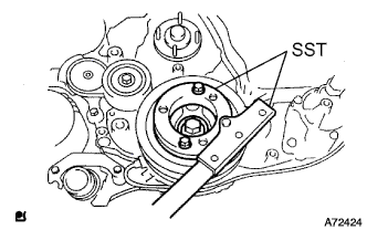
Fix the crankshaft with SST.
- SST
- 09213-58013
- 09330-00021
-
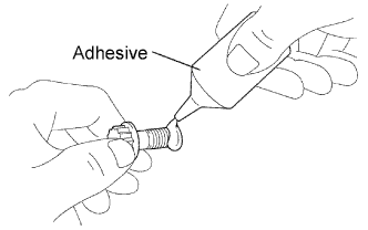
Apply adhesive to 2 or 3 threads of the 8 bolts.
Adhesive Toyota Genuine Adhesive 1344, Three Bond 1344 or equivalent -
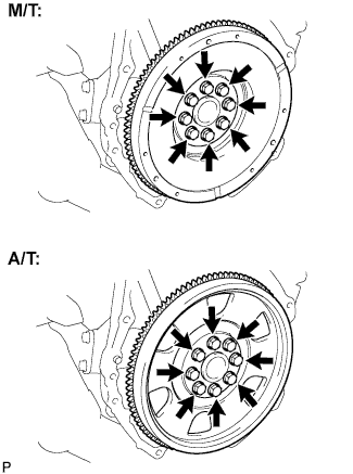
For manual transmission
-
Install the flywheel with the 8 bolts.
- Torque:
- 178 N*m { 1,815 kgf*cm, 131 ft.*lbf }
-
-
For automatic transmission.
-
Install the flywheel, drive plate and drive plate spacer rear with the 8 bolt.
- Torque:
- 178 N*m { 1,815 kgf*cm, 131 ft.*lbf }
-
-
-
INSTALL CLUTCH DISC ASSEMBLY (for Manual Transmission)
-
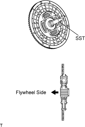
Insert SST into the clutch disc assembly, then insert them into the flywheel sub-assembly.
- SST
- 09301-00110
Note
Take care not to insert the clutch disc assembly in the wrong direction.
-
-
INSTALL CLUTCH COVER ASSEMBLY (for Manual Transmission)
-
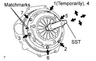
Align the matchmarks on the clutch cover assembly with the one on the flywheel sub-assembly.
-
Following the procedures shown in the illustration, tighten the 6 bolts starting from the bolt located near the knock pin on the top.
- SST
- 09301-00110
- Torque:
- 19 N*m { 195 kgf*cm, 14 ft.*lbf }
Tech Tips
-
Evenly tighten the bolts by following the order shown in the illustration.
-
Tighten the bolts after checking that the disc is in the center by lightly moving the SST up and down, left and right.
-
-
INSPECT AND ADJUST CLUTCH COVER ASSEMBLY (for Manual Transmission)
-
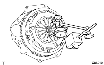
Using a dial indicator with a roller instrument, check the diaphragm spring tip alignment.
Maximum non-alignment 1.3 mm (0.051 in.) -
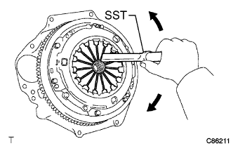
If alignment is not as specified, adjust the diaphragm spring tip alignment using SST.
- SST
- 09333-00013
-
-
INSTALL AUTOMATIC TRANSMISSION ASSEMBLY (for Automatic Transmission)
-
INSTALL MANUAL TRANSMISSION UNIT ASSEMBLY (for Manual Transmission)
-
INSTALL STARTER ASSEMBLY (for 2.0 kW Type)
-
Install the starter with the bolt and 2 nuts.
- Torque:
- 68 N*m { 693 kgf*cm, 50 ft.*lbf }
-
Connect the wire harness to terminal 30 and install the nut.
- Torque:
- 9.8 N*m { 100 kgf*cm, 87 in.*lbf }
-
Close the terminal cap.
-
Connect the terminal 50 connector to the starter assembly.
-
for Wide body:
Install the ground cable with the bolt.
- Torque:
- 25 N*m { 250 kgf*cm, 18 ft.*lbf }
-
-
INSTALL STARTER ASSEMBLY (for 2.2 kW Type)
-
Connect the wiring harness clamp bracket and install the starter assembly with the 2 bolts.
- Torque:
- 68 N*m { 693 kgf*cm, 50 ft.*lbf }
-
Install the starter wire with the nut.
- Torque:
- 9.8 N*m { 100 kgf*cm, 87 in.*lbf }
-
Connect the starter connector.
-
Install the No. 2 terminal cap.
-
-
INSTALL STARTER ASSEMBLY (for 2.7 kW Type)
-
Install the starter with the bolt and 2 nuts.
- Torque:
- 68 N*m { 693 kgf*cm, 50 ft.*lbf }
-
Connect the wire harness to terminal 30 and install the nut.
- Torque:
- 21 N*m { 215 kgf*cm, 16 ft.*lbf }
-
Close the terminal cap.
-
Connect the terminal 50 connector to the starter assembly.
-
for Wide Body:
Install the wire ground cable with the bolt.
- Torque:
- 25 N*m { 250 kgf*cm, 18 ft.*lbf }
-
-
INSTALL ENGINE ASSEMBLY WITH TRANSMISSION
-
Using a engine lifter, install the engine assembly w/ transmission to the vehicle.
-
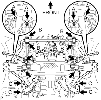
Install the stabilizer brackets and 16 bolts of the front suspension cross member.
- Torque:
- Bolt A
- 39 N*m { 398 kgf*cm, 29 ft.*lbf }
- Bolt B
- 36 N*m { 367 kgf*cm, 27 ft.*lbf }
- Bolt C
- 150 N*m { 1,530 kgf*cm, 111 ft.*lbf }
-
Connect the rear engine mount.
- Torque:
- 98 N*m { 1,000 kgf*cm, 72 ft.*lbf }
Note
Tighten the nut side when installing the mount.
-
Remove the engine lifter slowly.
-
-
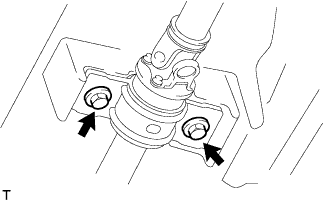
CONNECT STEERING TORQUE SHAFT ASSEMBLY
-
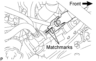
Align the matchmarks on the steering torque shaft assembly and the power steering link assembly.
-
Install bolt (B) and tighten the 2 bolts.
- Torque:
- 35 N*m { 360 kgf*cm, 26 ft.*lbf }
-
-
CONNECT OIL COOLER TUBE (for Automatic Transmission)
-
Connect the oil cooler inlet tube and oil cooler outlet tube with the clamp to the oil cooler.
-
-
INSTALL TRANSMISSION CONTROL CABLE ASSEMBLY (for Automatic Transmission)
-
Fix the transmission control cable assembly to the control cable bracket with a clip.
-
Install the transmission control cable assembly to the control shaft lever with the nut.
- Torque:
- 15 N*m { 150 kgf*cm, 11 ft.*lbf }
-
-
INSTALL TRANSMISSION OIL FILLER TUBE SUB-ASSEMBLY (for Automatic Transmission)
-
Coat a new O-ring with ATF and install the oil filler tube.
-
Install the oil filler tube with the 2 bolts.
- Torque:
- 12 N*m { 122 kgf*cm, 8 ft.*lbf }
-
-
INSTALL CLUTCH RELEASE CYLINDER ASSEMBLY (for Manual Transmission)
-
Install the clutch release cylinder with the 2 bolts.
- Torque:
- 12 N*m { 120 kgf*cm, 9 ft.*lbf }
-
-
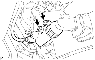
INSTALL TRANSMISSION CONTROL CABLE ASSEMBLY (for Manual Transmission)
-
Install 2 new clips to the transmission control cable bracket No.1.
-
Install the transmission control cable assembly to the transmission control cable bracket No.1.
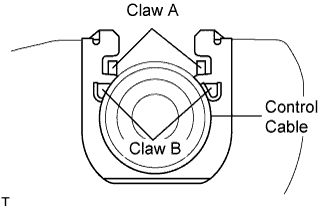
Note
-
Be sure that A claws of the clips are firmly engaged into the bracket grooves.
-
Be sure the cable is set in the clip with both B claws erected to prevent slippage of the cable in the opposite direction.
-
-
Align the matchmarks on the control cable assembly and the outer lever.
-
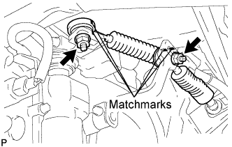
Install the transmission control cable assembly to the outer levers with the 2 nuts.
- Torque:
- 37 N*m { 377 kgf*cm, 27 ft.*lbf }
-
-
CONNECT SHOCK ABSORBER ASSEMBLY FRONT LH
-
CONNECT SHOCK ABSORBER ASSEMBLY FRONT RH
Tech Tips
Use the same procedures described for the LH side.
-
CONNECT FRONT SUSPENSION SUB-ASSEMBLY UPPER LH
-
Connect the front suspension upper arm to the steering knuckle with the nut.
- Torque:
- 113 N*m { 1,150 kgf*cm, 83 ft.*lbf }
-
Install a new cotter pin.
Note
-
If the holes for the cotter pin are not aligned, tighten the nut up to 60°.
-
Do not damage the ball joint dust cover.
-
-
-
CONNECT FRONT SUSPENSION SUB-ASSEMBLY UPPER RH
Tech Tips
Use the same procedures described for the LH side.
-
INSTALL FRONT DISC BRAKE CALIPER ASSEMBLY LH
-
Install the brake caliper assembly to the steering knuckle with the 2 bolts.
- Torque:
- 123 N*m { 1,250 kgf*cm, 91 ft.*lbf }
-
-
INSTALL FRONT DISC BRAKE CALIPER ASSEMBLY RH
Tech Tips
Use the same procedures described for the LH side.
-
INSTALL SPEED SENSOR FRONT LH (w/ ABS)
-
Install the speed sensor to the steering knuckle with the 2 bolts.
- Torque:
- 8.5 N*m { 87 kgf*cm, 75 in.*lbf }
Note
-
Prevent foreign matter from adhering to the speed sensor.
-
Be careful not to damage the speed sensor.
-
Do not twist the sensor wire when installing the speed sensor.
-
-
INSTALL SPEED SENSOR FRONT RH (w/ ABS)
Tech Tips
Use the same procedures described for the LH side.
-
INSTALL PROPELLER WITH CENTER BEARING SHAFT ASSEMBLY (for Super Long Wheelbase)
-
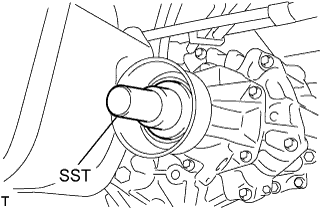
Remove the SST from the extension housing.
-
Install the propeller with center bearing shaft assembly in the extension housing.
-
Install the center support bearing assembly No.1, and temporarily tighten the 2 bolts.
-
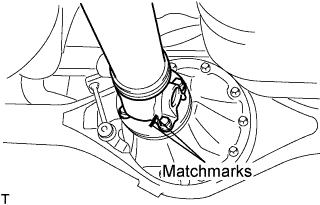
Align the matchmarks on the propeller shaft flange and differential flange.
-
Install the propeller shaft assembly with the 4 nuts, 4 bolts and 4 washers.
- Torque:
- 74 N*m { 755 kgf*cm, 54 ft.*lbf }
-
Check that the center line of the bracket is at right angles to the shaft axial direction.
-
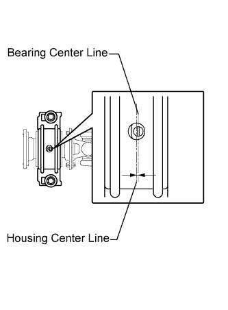
Adjust the center support bearing assembly No.1.
Tech Tips
-
With the vehicle unladen, adjust the center support bearing No.1 to maintain the angles, as shown.
-
In the same conditions, check the center line in the axial direction. Adjust the bearing if necessary.
-
The center bearing center line and center bearing housing center line must be adjusted to within -1.0 to 1.0 mm (-0.0394 to 0.0394 in.) of each other in the vehicle's longitudinal direction with the vehicle unladen.
-
-
Tighten the 2 bolts.
- Torque:
- 36 N*m { 369 kgf*cm, 27 ft.*lbf }
-
-
INSTALL PROPELLER SHAFT ASSEMBLY (for Long Wheelbase)
-
Remove the SST from the extension housing.
-
Install the propeller shaft assembly in the extension housing.
-
Align the matchmarks on the propeller shaft flange and differential flange.
-
Install the propeller shaft assembly with the 4 nuts, 4 bolts and 4 washers.
- Torque:
- 74 N*m { 755 kgf*cm, 54 ft.*lbf }
-
-
INSTALL EXHAUST PIPE ASSEMBLY CENTER (for Super Long Wheelbase)
-
Connect the exhaust pipe supports and install the exhaust pipe assembly center and a new gasket with the 2 bolts to the exhaust pipe assembly tail.
- Torque:
- 48 N*m { 489 kgf*cm, 35 ft.*lbf }
-
-
INSTALL EXHAUST PIPE ASSEMBLY FRONT (for Super Long Wheelbase)
-
Inspect the compression spring.
-
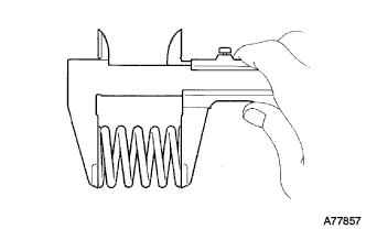
Using vernier calipers, measure the free length of the compression springs.
Minimum length 40.5mm(1.594 in.) Tech Tips
If the free length is less than the minimum, replace the compression spring.
-
-
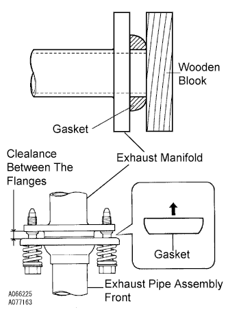
Install the gasket.
-
Fully insert a new gasket to the exhaust manifold by hand.
-
Using a wooden block, uniformly strike the gasket so that the gasket and exhaust manifold are properly fit.
Note
-
Be careful with the installation direction of the gasket.
-
Do not reuse the gasket.
-
Do not damage the gasket.
-
To ensure a proper seal, do not use the exhaust pipe assembly front to force the gasket onto the front exhaust manifold.
-
-
-
Connect the exhaust pipe support, and install the exhaust pipe assembly front and a new gasket with the 4 bolts, 2 compression springs and 2nuts.
- Torque:
- Exhaust manifold side
- 43 N*m { 438 kgf*cm, 32 ft.*lbf }
- Exhaust pipe assembly center side
- 48 N*m { 489 kgf*cm, 35 ft.*lbf }
Note
After installation, check that the clearance is almost same at any point between the flanges of the exhaust manifold and exhaust pipe assembly front .
-
-
INSTALL EXHAUST PIPE ASSEMBLY FRONT (for Long Wheelbase)
-
Inspect the compression spring.
-
Using vernier calipers, measure the free length of the compression springs.
Minimum length 40.5mm (1.594 in.) Tech Tips
If the free length is less than the minimum, replace the compression spring.
-
-
Install the gasket.
-
Fully insert a new gasket to the exhaust manifold by hand.
-
Using a wooden block, uniformly strike the gasket so that the gasket and exhaust manifold are properly fit.
Note
-
Be careful with the installation direction of the gasket.
-
Do not reuse the gasket.
-
Do not damage the gasket.
-
To ensure a proper seal, do not use the exhaust pipe assembly front to force the gasket onto the front exhaust manifold.
-
-
-
Connect the exhaust pipe support, and install the exhaust pipe assembly front with the 4 bolts, 2 compression springs and 2 nuts.
- Torque:
- exhaust manifold side
- 43 N*m { 438 kgf*cm, 32 ft.*lbf }
- exhaust pipe assembly front side
- 48 N*m { 489 kgf*cm, 35 ft.*lbf }
Note
After installation, check that the clearance is almost same at any point between the flanges of the exhaust manifold and exhaust pipe assembly front.
-
-
INSTALL VANE PUMP OIL RESERVOIR ASSEMBLY
-
Install the vane pump oil reservoir assembly with the 2 bolts.
- Torque:
- 8.0 N*m { 82 kgf*cm, 71 in.*lbf }
-
-
INSTALL COMPRESSOR AND MAGNETIC CLUTCH (w/ Air Conditioning System)
-
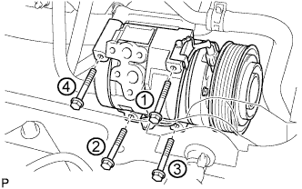
Provisionally tighten the compressor and magnetic clutch with the 4 bolts.
-
Tighten the compressor and magnetic clutch with the 4 bolts.
- Torque:
- 25 N*m { 255 kgf*cm, 18 ft.*lbf }
Note
Tighten the bolts in the order shown in the illustration to install the compressor and magnetic clutch.
-
-
CONNECT ENGINE WIRE
-
Connect the +B terminal and connector of the starter.
- Torque:
- M8 nut
- 9.8 N*m { 100 kgf*cm, 87 in.*lbf }
- M10 nut
- 21 N*m { 215 kgf*cm, 16 ft.*lbf }
-
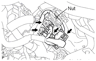
Install the 4 connectors and nut as shown in the illustration.
-
Connect the clamps of the engine wire and earth cable.
-
Connect the ECM connector Click here.
-
-
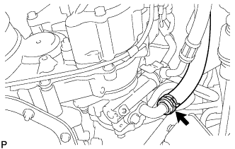
CONNECT VACUUM HOSE
-
Connect the vacuum hose to the vacuum pump assembly.
-
-
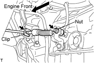
CONNECT FUEL HOSE NO.1
-
Connect the fuel hose No.1 with the clamp to the injection pump assembly.
-
-
CONNECT FUEL HOSE NO.2
-
Connect the fuel hose No.2 with the clamp to the nozzle leakage pipe No.2.
-
-
CONNECT WATER BY-PASS HOSE NO.3
-
Connect the water by-pass hose No.3 with the clamp to the water by-pass pipe No.2.
-
-
CONNECT RADIATOR HOSE NO.4
-
Connect the radiator hose No.4 with the clamp to the water outlet.
-
-
CONNECT RADIATOR HOSE INLET
-
Connect the radiator inlet hose with the clamp to the water inlet.
-
-
CONNECT AIR HOSE NO.4
-
Connect the air hose No.4 with the clamp to the diesel throttle body.
-
-
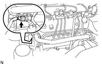
CONNECT OIL RETURN HOSE (w/ Intercooler)
-
Connect the oil return hose to the intake manifold.
-
-
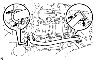
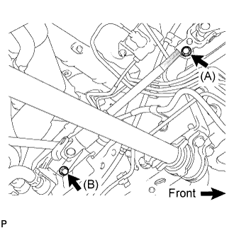
INSTALL COMPRESSOR OUTLET ELBOW
-
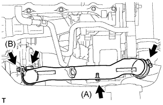
Install the compressor outlet elbow with the 2 bolts and 2 clamps.
- Torque:
- Bolt (A)
- 12 N*m { 122 kgf*cm, 9 ft.*lbf }
- Bolt (B)
- 32 N*m { 326 kgf*cm, 24 ft.*lbf }
-
-
INSTALL AIR CLEANER HOSE ASSEMBLY
-
Install the air cleaner hose assembly with the clamp.
-
-
INSTALL FENDER APRON MUDGUARD SEAL
-
INSTALL FAN & GENERATOR V BELT
-
Rotate the V-ribbed belt tensioner pulley clockwise, and then install the fan and generator V belt.
Note
Make sure that the fan and generator V belt is set properly on each pulley.
-
Check that the indicator mark of the V-ribbed belt tensioner Click here.
-
-
INSTALL ENGINE SERVICE HOLE SUB COVER ASSEMBLY
-
Install the engine service hole sub cover with the 5 bolts.
- Torque:
- 13 N*m { 133 kgf*cm, 10 ft.*lbf }
-
-
INSTALL FRONT DOOR SCUFF PLATE
-
INSTALL FRONT SEAT ASSEMBLY RH (for Hi-back Seat Type)
-
Perform the same procedure as above on the opposite side. Click here
-
-
INSTALL FRONT SEAT ASSEMBLY RH (for Low-back Seat Type)
-
Perform the same procedure as above on the opposite side. Click here
-
-
CONNECT BATTERY NEGATIVE CABLE
-
INSTALL FRONT WHEELS
- Torque:
- 103 N*m { 1,050 kgf*cm, 76 ft.*lbf }
-
PLACE FRONT WHEELS FACING STRAIGHT AHEAD
-
ADD ENGINE OIL
-
ADD ENGINE COOLANT
-
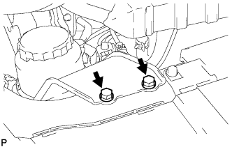
Firmly tighten the drain plugs.
-
Fill the radiator reservoir assembly with engine coolant to the top of the inlet.
Standard Capacity Item Specified Condition w/o Heater 13.2 liters (13.9 US qts, 11.6 Imp. qts) w/ Front Heater 14.2 liters (15.0 US qts, 12.5 Imp. qts) w/ Front and Rear Heaters 16.2 liters (17.1 US qts, 14.3 Imp. qts) Note
Do not substitute plain water for engine coolant.
Tech Tips
-
Use of improper coolants may damage the engine cooling system.
-
Use only Toyota Super Long Life Coolant or similar high quality ethylene glycol based non-silicate, non-amine, non-nitrite, and non-borate coolant with long-life hybrid organic acid technology (coolant with long-life hybrid organic acid technology consists of a combination of low phosphates and organic acids).
-
-
Loosen the bleeder plug of the outlet housing.
-
When air is bled and the engine coolant drains out, firmly tighten the bleeder plug.
- Torque:
- 8.0 N*m { 82 kgf*cm, 71 in.*lbf }
-

Add engine coolant up to the B line mark in the radiator reservoir assembly and install the radiator reservoir cap sub-assembly.
-
Warm up the engine until the thermostat opens.
-
While the thermostat is open, circulate the engine coolant for several minutes.
Tech Tips
The thermostat open timing can be confirmed by pressing the No. 3 radiator hose by hand, and checking when the engine coolant starts to flow inside the hose.
-
-

After the engine cools down, check that the engine coolant level is between the LOW and FULL level marks.
-
-
ADD POWER STEERING FLUID
-
BLEED FUEL LINE
-
Push the priming pump for several times to fill up the fuel lines with fuel.
-
-
BLEED POWER STEERING FLUID
-
Check the fluid level.
-
Jack up the front of the vehicle and support it with stands.
-
Turn the steering wheel.
-
With the engine stopped, turn the steering wheel slowly from lock to lock several times.
-
-
Lower the vehicle.
-
Start the engine.
-
Run the engine at idle for a few minutes.
-
-
Turn the steering wheel.
-
With the engine idling, turn the steering wheel left or right to the full lock position and keep it there for 2 to 3 seconds, then turn the steering wheel to the opposite full lock position and keep it there for 2 to 3 seconds.
-
Repeat several times.
-
-
Stop the engine.
-
Check for foaming or emulsification.
If the system has to be bled twice because of forming or emulsification, be sure to check for fluid leaks in the system.
-
Check the fluid level Click here.
-
-
INSPECT FUEL LEAK
-
PERFORM ACTIVE TEST
-
Connect the intelligent tester to the DLC3.
-
Turn the ignition switch on.
-
Turn the intelligent tester on.
-
Enter the following menus: Powertrain / ECD / Active Test.
-
Perform the Active Test.
Intelligent Tester Display Test Details Control Range Diagnostic Notes Test the Fuel Leak Pressurizes common rail internal fuel pressure, and checks for fuel leaks Stop/Start
-
Fuel pressure inside common rail pressurized to specified value and engine speed increased to 2,000 rpm when ON is selected
-
Above conditions preserved while test is ON
-
-
-
-
INSPECT ENGINE OIL LEAKS
-
INSPECT ENGINE COOLANT LEAKS
CAUTION:
Do not remove the radiator cap while the engine and radiator are still hot. Pressurized, hot engine coolant and steam may be released and cause serious burns.
-
Fill the radiator with coolant and attach a radiator cap tester to the radiator.
-
Warm up the engine.
-
Using a radiator cap tester, increase the pressure inside the radiator to 137 kPa (1.4 kgf/cm2, 19.9 psi), and check that the pressure does not drop.
Tech Tips
If the pressure drops, check the hoses, radiator or water pump for leaks. If no external leaks are found, check the heater core, cylinder block and cylinder head.
-
-
INSPECT POWER STEERING FLUID LEAK
-
INSPECT POWER STEERING FLUID LEVEL
-
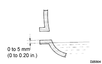
INSPECT MANUAL TRANSMISSION OIL (for Manual Transmission)
-
Park the vehicle in a level place.
-
Remove the transmission filler plug and gasket.
-
Check that the oil surface is within 5 mm (0.20 in.) below the lowest point of the transmission filler plug opening.
Oil grade GL-4 Viscosity SAE 75W-90 Capacity 2.6 liters (2.7 US qts, 2.3 lmp.qts) Note
-
Problems may occur when the oil level is too high or too low.
-
After replacing the oil, drive the vehicle and check the oil level again.
-
-
Check for oil leakage if the oil level is low.
-
Install the transmission filler plug and a new gasket.
- Torque:
- 37 N*m { 377 kgf*cm, 27 ft.*lbf }
-
-
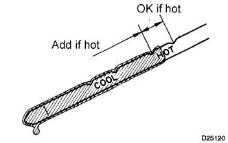
INSPECT AUTOMATIC TRANSMISSION FLUID (for Automatic Transmission)
Tech Tips
Drive the vehicle so that the engine and transmission are at normal operating temperature.
Fluid temperature 70 to 80 °C (158 to 176 °F)
-
Park the vehicle on a level surface and set the parking brake.
-
With the engine idling and the brake pedal depressed, move shift the lever into all positions from P to L and return to the P position.
-
Take out the dipstick and wipe it clean.
-
Put it back all the way.
-
Take it out again and check that the fluid level is within the HOT range.
If the fluid level is below the HOT range, add new fluid and recheck the fluid level. If the fluid level exceeds the HOT range, drain the fluid once, add the proper amount of new fluid and recheck the fluid level.
-
-
INSPECT SHIFT LEVER POSITION (for Automatic Transmission)
-
When shifting from P position only with ignition switch ON and depress the break pedal.
-
Make sure that the shifting lever moves smoothly and can be moderately operated.
-
When starting engine, make sure that the vehicle moves forward when shifting from N to D position and moves reward when shifting R position.
-
-
ADJUST SHIFT LEVER POSITION (for Automatic Transmission)
-
Remove a clip, nut, and disconnect between the control shaft lever to transmission control cable assembly from the control shaft lever and transmission control cable bracket No.1.
-
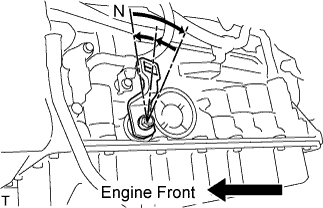
Turn the control shaft lever until stop to a clockwise direction, return the control shaft lever 2 notches to N position.
-

Set the shift lever to N position while holding the shift lever lightly toward the R position side and install it.
- Torque:
- 15 N*m { 150 kgf*cm, 11 ft.*lbf }
Note
Tighten the nut with it closing up cranky.
-
Inspect the operation condition and work.
-
-
INSPECT EXHAUST GAS LEAKS
-
ADJUST FRONT WHEEL ALIGNMENT
-
INSTALL ENGINE SIDE UNDER COVER RH (w/ Engine Side Under Cover RH)
- Torque:
- 13 N*m { 133 kgf*cm, 10 ft.*lbf }
-
INSTALL ENGINE SIDE UNDER COVER LH (w/ Engine Side Under Cover LH)
- Torque:
- 13 N*m { 133 kgf*cm, 10 ft.*lbf }
-
INSTALL ENGINE UNDER COVER NO.2 (w/ Engine Under Cover No.2)
- Torque:
- 13 N*m { 133 kgf*cm, 10 ft.*lbf }
-
INSTALL ENGINE UNDER COVER NO.1 (w/ Engine Under Cover No.1)
- Torque:
- 13 N*m { 133 kgf*cm, 10 ft.*lbf }
-
CHECK IDLE SPEED
Note
This checking procedure should be done under the following condition.
Tech Tips
-
Regarding the details about the intelligent tester, refer to its operator's manual.
-
If the intelligent tester is not available, a tachometer's tester probe can substitute for it.
-
Connect the intelligent tester to the DLC3.
-
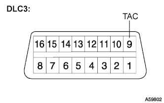
If the tester is not available, connect a tester probe of a tachometer to terminal 9 (TAC) of the DLC3 with SST.
- SST
- 09843-18030
-
Start the engine and check the idle speed.
Idle speed 700 to 800 rpm Tech Tips
If the idle speed is not as specified, check by troubleshooting in the diagnostics section.
-
In case of the tester probe of the tachometer is connected to the DLC3, disconnect the tester probe from terminal 9 of the DLC3 with SST.
-
Disconnect the intelligent tester from the DLC3.
-
-
INSPECT MAXIMUM ENGINE SPEED
Note
This checking procedure should be done under the following condition.
Tech Tips
-
Regarding the details about the intelligent tester, refer to its operator's manual.
-
If the intelligent tester is not available, a tachometer's tester probe can substitute for it.
-
Connect the intelligent tester to the DLC3.
-
If the tester is not available, connect a tester probe of a tachometer to terminal 9 (TAC) of the DLC3 with SST.
- SST
- 09843-18030
-
Start the engine.
-
Depress the accelerator pedal all the way to the limit.
-
Check the maximum speed.
Maximum speed 4500 to 4700 rpm Tech Tips
If the maximum speed is not as specified, check by troubleshooting in the diagnostics section.
-
In case of the tester probe of the tachometer is connected to the DLC3, disconnect the tester probe from terminal 9 of the DLC3 with SST.
-
Disconnect the intelligent tester from the DLC3.
-
-
INSPECT ABS SENSOR SIGNAL
-
INSPECT FUNCTION OF THROTTLE BODY
-
Inspect the throttle control motor.
-
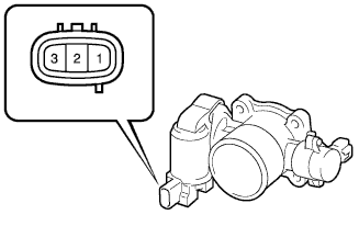
Using an ohmmeter, measure the resistance between the terminals.
Standard resistance Tester Connection Specified Condition 1 (DUTY) - Body ground Infinity
-
-
-
PERFORM INITIALIZATION