CYLINDER HEAD INSTALLATION

Note
-
When replacing the injectors (including shuffling the injectors between the cylinders), common rail or cylinder head, it is necessary to replace the injection pipes with new ones.
-
When replacing the fuel supply pump, common rail, cylinder block, cylinder head, cylinder head gasket or timing gear case, it is necessary to replace the fuel inlet pipe with a new one.
-
INSTALL CYLINDER HEAD GASKET
-
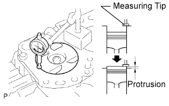
Find where the piston head protrudes most by slowly turning the crankshaft clockwise and counterclockwise.
-
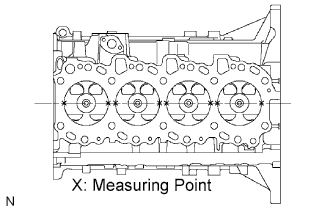
Measure the piston protrusion of each cylinder at 2 points as shown in the illustration.
-
For the piston protrusion value of each cylinder, use the average of the 2 measurements of that cylinder.
Standard piston protrusion 0.005 to 0.254 mm (0.0002 to 0.0100 in.) Tech Tips
If the protrusion is not as specified, remove the piston and connecting rod assembly and reinstall them.
-
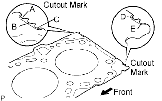
Select a new cylinder head gasket.
Tech Tips
New cylinder head gaskets are available in 5 sizes, and are marked A, B, C, D or E.
New Installed Cylinder Head Gasket Thickness Item Specified Condition Mark A 0.80 to 0.90 mm (0.0315 to 0.0354 in.) Mark B 0.85 to 0.95 mm (0.0335 to 0.0374 in.) Mark C 0.90 to 1.00 mm (0.0354 to 0.0394 in.) Mark D 0.95 to 1.05 mm (0.0374 to 0.0413 in.) Mark E 1.00 to 1.10 mm (0.0394 to 0.0433 in.)
-
Select the largest piston protrusion value from the measurements made. Then select a new appropriate gasket according to the table below.
Gasket Size to be Used Gasket Size Piston Protrusion A 0.005 to 0.054 mm (0.0002 to 0.0021 in.) B 0.055 to 0.104 mm (0.0022 to 0.0041 in.) C 0.105 to 0.154 mm (0.0041 to 0.0061 in.) D 0.155 to 0.204 mm (0.0061 to 0.0080 in.) E 0.205 to 0.255 mm (0.0081 to 0.0100 in.)
-
-
Place the cylinder head on the cylinder block.
-
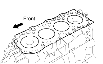
Place the cylinder head gasket on the cylinder block.
Note
Make sure the gasket is installed in the collect direction.
-
Place the cylinder head on the cylinder head gasket.
-
-
-
INSTALL CYLINDER HEAD SUB-ASSEMBLY
Tech Tips
-
The cylinder head bolts are tightened in 3 progressive steps.
-
If any bolt is broken or deformed, replace it.
-
Apply a light coat of engine oil to the threads and under the heads of the cylinder head bolts.
-
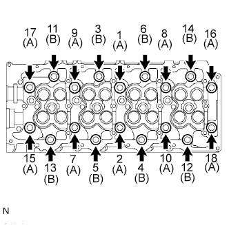
Install and uniformly tighten the 18 cylinder head bolts and 18 washers in several passes in the sequence shown in the illustration.
- Torque:
- 85 N*m { 867 kgf*cm, 63 ft.*lbf }
Bolt Length A 110 mm (4.33 in.) B 167 mm (6.57 in.) If any of the cylinder head bolts does not meet the torque specification, replace it.
-
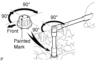
Mark the front of the cylinder head bolts with paint.
-
Further tighten the cylinder head bolts by 90° in the sequence shown in the illustration above.
-
Finally, tighten the cylinder head bolts by an additional 90°.
-
Check that the painted marks are now facing rearward.
-
-
INSTALL EXHAUST MANIFOLD
-
Set a new gasket on the cylinder head.
-
Install the exhaust manifold, 8 washers, 8 collars with 8 new nuts.
- Torque:
- 40 N*m { 408 kgf*cm, 30 ft.*lbf }
Note
Install the collars so that the side with the smaller external diameter faces the exhaust manifold.
-
-
INSTALL INTAKE MANIFOLD
-
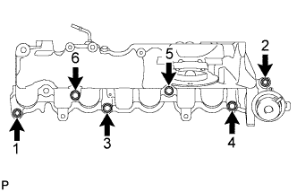
Temporarily install a new gasket and the intake manifold with the 2 nuts and 4 bolts.
-
Tighten the 2 nuts and 4 bolts in the order shown in the illustration.
- Torque:
- 29 N*m { 296 kgf*cm, 21 ft.*lbf }
Note
Make sure that the swirl control valve actuator is not damaged by the surrounding parts.
-
-
INSTALL MANIFOLD STAY
-
Install the manifold stay with the 2 bolts.
- Torque:
- 19 N*m { 194 kgf*cm, 14 ft.*lbf }
-
-
INSTALL CYLINDER BLOCK INSULATOR
-
Install the cylinder block insulator to the cylinder head.
-
-
INSTALL CAMSHAFT
-
INSPECT VALVE CLEARANCE
-
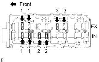
Check only the valves indicated.
-
Using a feeler gauge, measure the clearance between the valve lifter and camshaft.
Standard Valve Clearance (Cold) Item Specified Condition Intake 0.20 to 0.30 mm (0.008 to 0.012 in.) Exhaust 0.35 to 0.45 mm (0.014 to 0.018 in.) Write down any valve clearance measurements that are not within the specified range. These measurements will be used later to determine the size of the adjustment lifter to be installed.
-
-
Turn the crankshaft 360° to set the No. 4 cylinder to TDC/compression.
-
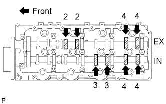
Check only the valves indicated.
-
Using a feeler gauge, measure the clearance between the valve lifter and camshaft.
Standard Valve Clearance Item Specified Condition Intake 0.20 to 0.30 mm (0.008 to 0.012 in.) Exhaust 0.35 to 0.45 mm (0.014 to 0.018 in.) Write down any valve clearance measurements that are not within the specified range. These measurements will be used later to determine the size of the adjustment lifter to be installed.
-
-
-
ADJUST VALVE CLEARANCE
-
Remove the camshafts Click here.
-
Remove the valve lifters.
-
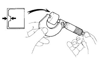
Using a micrometer, measure the thickness of the removed lifter.
-
Calculate the thickness of a new lifter so that the valve clearance is within the specified range.
A B C New lifter thickness Used lifter thickness Measured valve clearance New lifter thickness Intake A = B + (C - 0.25 mm (0.0098 in.)) Exhaust A = B + (C - 0.40 mm (0.00158 in.)) -
Select a new lifter with a thickness as close as possible to the calculated values.
Tech Tips
Valve lifters are available in 35 sizes in increments of 0.020 mm (0.0008 in.), from 5.060 mm (0.1992 in.) to 5.740 mm (0.2260 in.).
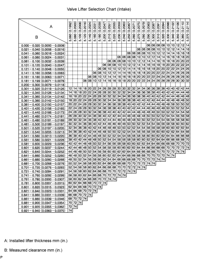
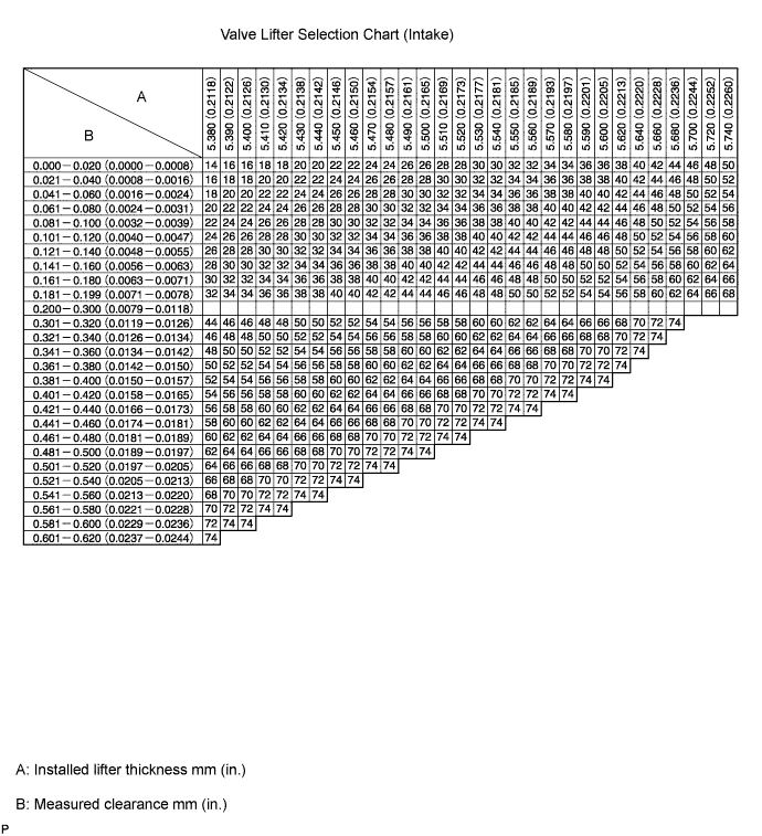
Standard intake valve clearance (Cold) 0.20 to 0.30 mm (0.008 to 0.012 in.) EXAMPLE A 5.250 mm (0.2067 in.) lifter is installed, and the measured clearance is 0.400 mm (0.0158 in.). Replace the 5.250 mm (0.2067 in.) lifter with a No. 40 lifter. New Lifter Thickness Lifter No. Specified Condition Lifter No. Specified Condition Lifter No. Specified Condition 06 5.060 mm (0.1992 in.) 30 5.300 mm (0.2087 in.) 54 5.540 mm (0.2181 in.) 08 5.080 mm (0.2000 in.) 32 5.320 mm (0.2094 in.) 56 5.560 mm (0.2189 in.) 10 5.100 mm (0.2008 in.) 34 5.340 mm (0.2102 in.) 58 5.580 mm (0.2197 in.) 12 5.120 mm (0.2016 in.) 36 5.360 mm (0.2110 in.) 60 5.600 mm (0.2205 in.) 14 5.140 mm (0.2024 in.) 38 5.380 mm (0.2118 in.) 62 5.620 mm (0.2213 in.) 16 5.160 mm (0.2031 in.) 40 5.400 mm (0.2126 in.) 64 5.640 mm (0.2220 in.) 18 5.180 mm (0.2039 in.) 42 5.420 mm (0.2134 in.) 66 5.660 mm (0.2228 in.) 20 5.200 mm (0.2047 in.) 44 5.440 mm (0.2142 in.) 68 5.680 mm (0.2236 in.) 22 5.220 mm (0.2055 in.) 46 5.460 mm (0.2150 in.) 70 5.700 mm (0.2244 in.) 24 5.240 mm (0.2063 in.) 48 5.480 mm (0.2157 in.) 72 5.720 mm (0.2252 in.) 26 5.260 mm (0.2071 in.) 50 5.500 mm (0.2165 in.) 74 5.740 mm (0.2260 in.) 28 5.280 mm (0.2079 in.) 52 5.520 mm (0.2173 in.) - - 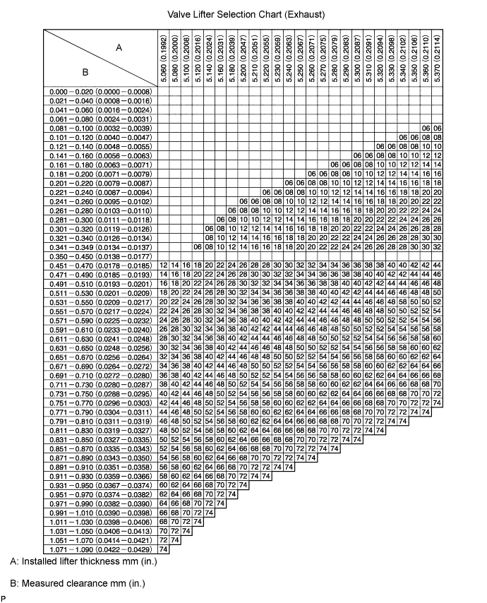
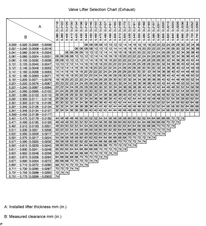
Standard exhaust valve clearance (Cold) 0.35 to 0.45 mm (0.014 to 0.018 in.) EXAMPLE A 5.340 mm (0.2102 in.) lifter is installed, and the measured clearance is 0.480 mm (0.0189 in.). Replace the 5.340 mm (0.2102 in.) lifter with a No. 42 lifter. New Lifter Thickness Lifter No. Specified Condition Lifter No. Specified Condition Lifter No. Specified Condition 06 5.060 mm (0.1992 in.) 30 5.300 mm (0.2087 in.) 54 5.540 mm (0.2181 in.) 08 5.080 mm (0.2000 in.) 32 5.320 mm (0.2094 in.) 56 5.560 mm (0.2189 in.) 10 5.100 mm (0.2008 in.) 34 5.340 mm (0.2102 in.) 58 5.580 mm (0.2197 in.) 12 5.120 mm (0.2016 in.) 36 5.360 mm (0.2110 in.) 60 5.600 mm (0.2205 in.) 14 5.140 mm (0.2024 in.) 38 5.380 mm (0.2118 in.) 62 5.620 mm (0.2213 in.) 16 5.160 mm (0.2031 in.) 40 5.400 mm (0.2126 in.) 64 5.640 mm (0.2220 in.) 18 5.180 mm (0.2039 in.) 42 5.420 mm (0.2134 in.) 66 5.660 mm (0.2228 in.) 20 5.200 mm (0.2047 in.) 44 5.440 mm (0.2142 in.) 68 5.680 mm (0.2236 in.) 22 5.220 mm (0.2055 in.) 46 5.460 mm (0.2150 in.) 70 5.700 mm (0.2244 in.) 24 5.240 mm (0.2063 in.) 48 5.480 mm (0.2157 in.) 72 5.720 mm (0.2252 in.) 26 5.260 mm (0.2071 in.) 50 5.500 mm (0.2165 in.) 74 5.740 mm (0.2260 in.) 28 5.280 mm (0.2079 in.) 52 5.520 mm (0.2173 in.) - - -
Install the selected valve lifters.
-
Install the camshafts Click here.
-
-
INSTALL TURBOCHARGER SUB-ASSEMBLY
-
INSTALL FRONT EXHAUST PIPE ASSEMBLY
-
INSTALL GLOW PLUG ASSEMBLY
-
INSTALL COMMON RAIL ASSEMBLY
-
INSTALL INJECTOR ASSEMBLY
-
INSTALL EGR COOLER ASSEMBLY
-
INSTALL TIMING BELT
-
ADD ENGINE OIL
-
Add new engine oil.
Engine Oil Oil Grade Oil Viscosity (SAE) G-DLD-1, API CF-4 or CF, ACEA B1 5W-30
10W-30
15W-40
20W-50
Capacity Item Fill Amount Drain and refill without oil filter change 6.8 liters (7.2 US qts, 6.0 Imp. qts) Drain and refill with oil filter change 7.0 liters (7.4 US qts, 6.2 Imp. qts) Dry fill 7.7 liters (8.1 US qts, 6.8 Imp. qts) -
Install the oil filler cap.
-
-
INSPECT FOR OIL LEAK
-
Start the engine. Make sure that there are no oil leaks from the areas that were worked on.
-
-
INSPECT ENGINE OIL LEVEL
-
Warm up the engine, stop the engine and wait for 5 minutes.
-
Check that the oil level is between the upper level and lower level of the engine oil level dipstick.
If the oil level is low, check for leakage and add oil up to the upper level of the oil level dipstick.
-