TIMING BELT INSTALLATION

-
INSTALL NO.1 TIMING BELT IDLER SUB-ASSEMBLY
-
Using a 10 mm hexagon wrench, install a new washer and the timing belt idler with the bolt.
- Torque:
- 35 N*m { 357 kgf*cm, 26 ft.*lbf }
Note
Do not reuse the washer.
-
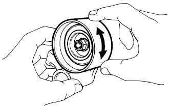
Check that the idler pulley can be turned smoothly by hand.
If it does not move smoothly, check the idler sub-assembly.
-
-
INSTALL TIMING BELT
-
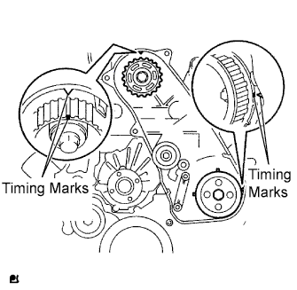
Check that the timing marks are aligned as shown in the illustration.
Tech Tips
If reusing the timing belt, align the matchmarks marked during removal, and install the belt with the direction arrow pointing in the direction of engine revolution.
Note
-
The engine should be cold.
-
When turning the crankshaft, the valve heads will hit against the piston's top position. Do not turn it more than necessary.
-
-
Install the timing belt to pump drive shaft pulley, camshaft timing pulley and No.1 timing belt idler in sequence.
-
Place the tensioner upright into a press. Then set the press to the top of tensioner.
Note
-
Do not scratch and deform the rod end.
-
Press the tensioner rod in upward.
-
Protect the tip of the push rod with a shop rag or piece of cloth in order to prevent damage.
-
-
Using the press, slowly apply 981 to 9,807 N (100 to 1,000 kgf, 220 to 2,205 lbf) of force to the push rod.
Note
Do not apply a load of 981 to 9807 N (100 to 1000 kgf, 220 to 2205 lbf) or more to the push rod.
-
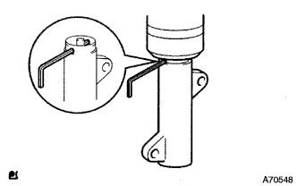
Align the holes of the push rod and housing and pass a 1.27 mm hexagon wrench through the holes to keep the setting position of the push rod.
-
Temporarily install the timing belt tensioner with the 2 bolts while pushing the idler pulley toward the timing belt.
-
Tighten the 2 bolts.
- Torque:
- 13 N*m { 133 kgf*cm, 10 ft.*lbf }
Note
Uniformly tighten the 2 bolts when installing the tensioner
-
Remove the 1.27 mm hexagon wrench from the tensioner.
-
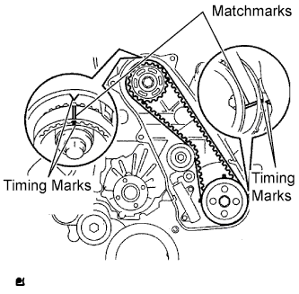
Turn the crankshaft clockwise 720° and check that the timing marks are aligned as shown in the illustration.
-
-
INSTALL NO. 1 TIMING BELT COVER
-
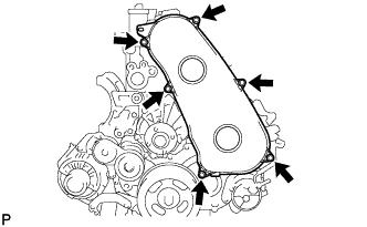
Install the No.1 timing belt cover with the 6 bolts.
- Torque:
- 6.0 N*m { 61 kgf*cm, 53 in.*lbf }
-
Install the wire harness clamp.
-
-
INSTALL RADIATOR HOSE INLET
-
INSTALL W/ PULLEY COMPRESSOR ASSEMBLY (w/ Air Conditioning System)
-
INSTALL COMPRESSOR OUTLET ELBOW
-
INSTALL FAN & GENERATOR V BELT
-
Rotate the V-ribbed belt tensioner pulley clockwise, and then install the fan and generator V belt.
Note
Make sure that the fan and generator V belt is set properly on each pulley.
-
Check that the indicator mark of the V-ribbed belt tensioner Click here.
-
-
INSTALL ENGINE SERVICE HOLE SUB COVER SUB-ASSEMBLY
-
Install the engine service hole sub cover with the 5 bolts.
- Torque:
- 13 N*m { 133 kgf*cm, 10 ft.*lbf }
-
-
INSTALL FRONT SEAT ASSEMBLY RH
-

Connect the front seat inner belt assembly connector and install the front seat assembly.
-
Align the front seat assembly adjuster pin with the holes in the body.
-
Move the front seat assembly to the rearmost position.
Note
Make sure that the front seat assembly is securely locked.
-
Temporarily tighten the 2 bolts on the front side of the front seat assembly.
-
Move the front seat assembly fully forward.
Note
Make sure that the front seat assembly is securely locked.
-
Temporarily tighten the 2 bolts on the rear side of the front seat assembly.
-
Move the front seat assembly to the rearmost position.
Note
Make sure that the front seat assembly is securely locked.
-
Fully tighten the 2 bolts on the front side of the front seat assembly in the order of outer and inner side.
- Torque:
- 39 N*m { 398 kgf*cm, 29 ft.*lbf }
-
Move the front seat assembly fully forward.
Note
Make sure that the front seat assembly is securely locked.
-
Fully tighten the 2 bolts on the rear side of the front seat assembly in the order of outer and inner side.
- Torque:
- 39 N*m { 398 kgf*cm, 29 ft.*lbf }
-
-
INSTALL FRONT DOOR SCUFF PLATE RH