TIMING BELT INSTALLATION

-
INSTALL NO. 1 TIMING BELT IDLER SUB-ASSEMBLY
-
Using a 10 mm hexagon wrench, install a new washer and the No. 1 timing belt idler with the bolt.
- Torque:
- 35 N*m { 357 kgf*cm, 26 ft.*lbf }
Note
Do not reuse the washer.
-
Check that the idler pulley moves smoothly.
If the idler pulley does not move smoothly, check the installation condition of the idler and washer.
-
-
INSTALL TIMING BELT
-
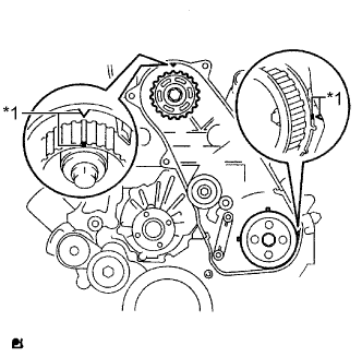
Text in Illustration *1 Timing Mark Check that the timing marks are aligned as shown in the illustration.
Note
-
Make sure that the engine is cold.
-
When turning the crankshaft, the valve heads will hit against the piston. Do not turn the crankshaft more than necessary.
Tech Tips
If reusing the timing belt, align the points marked during removal, and install the belt with the arrow pointing in the direction of crankshaft revolution.
-
-
Install the timing belt to the pump drive shaft pulley, camshaft timing pulley and No. 1 timing belt idler in sequence.
-
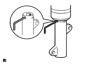
Place the tensioner upright. Then set a press on the top of the tensioner.
Note
-
Do not scratch or deform the rod end.
-
Press in the tensioner rod.
-
Protect the tip of the push rod with a cloth in order to prevent damage.
-
-
Using the press, slowly push in the push rod using 981 to 9800 N (100 to 999 kgf, 220 to 2203 lbf) of force.
Note
Do not apply a load of over 9800 N (999 kgf, 2203 lbf) to the push rod.
-
Align the holes of the push rod and housing. Then pass a 1.5 mm hexagon wrench through the holes to fix the push rod in place.
-
Temporarily install the timing belt tensioner with the 2 bolts while pushing the idler pulley toward the timing belt.
-
Tighten the 2 bolts.
- Torque:
- 13 N*m { 133 kgf*cm, 10 ft.*lbf }
Note
Uniformly tighten the 2 bolts.
-
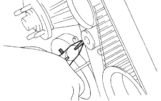
Remove the 1.5 mm hexagon wrench from the tensioner.
-
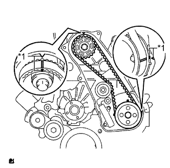
Text in Illustration *1 Timing Mark Turn the crankshaft clockwise 720° and check that the timing marks are aligned as shown in the illustration.
-
-
INSTALL NO. 1 TIMING BELT COVER
-
Install the timing belt cover and 6 washers with the 6 bolts.
- Torque:
- 6.0 N*m { 61 kgf*cm, 53 in.*lbf }
-
Install the wire harness clamp.
-
-
INSTALL RADIATOR HOSE INLET
-
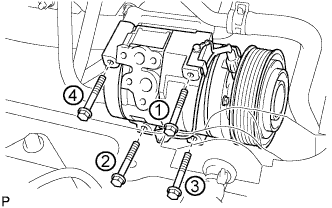
INSTALL COMPRESSOR ASSEMBLY WITH PULLEY (w/ Air Conditioning System)
-
Provisionally tighten the compressor and magnetic clutch with the 4 bolts.
-
Tighten the compressor and magnetic clutch with the 4 bolts.
- Torque:
- 25 N*m { 255 kgf*cm, 18 ft.*lbf }
Note
Tighten the bolts in the order shown in the illustration to install the compressor and magnetic clutch.
-
-
INSTALL COMPRESSOR OUTLET ELBOW
-
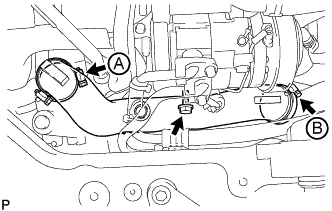
Install the compressor outlet elbow with the 2 hose clamps and bolt.
- Torque:
- for bolt
- 12 N*m { 122 kgf*cm, 9 ft.*lbf }
- for hose clamp A
- 6.5 N*m { 66 kgf*cm, 58 in.*lbf }
- for hose clamp B
- 6.0 N*m { 61 kgf*cm, 53 in.*lbf }
-
-
INSTALL FAN AND GENERATOR V BELT
-
Rotate the V-ribbed belt tensioner pulley clockwise, and then install the fan and generator V belt.
Note
Make sure that the fan and generator V belt is set properly on each pulley.
-
Check that the indicator mark of the V-ribbed belt tensioner Click here.
-
-
INSTALL ENGINE SERVICE HOLE SUB COVER SUB-ASSEMBLY
-
Install the engine service hole sub cover with the 5 bolts.
- Torque:
- 13 N*m { 133 kgf*cm, 10 ft.*lbf }
-
-
INSTALL FRONT SEAT ASSEMBLY RH
-

Connect the front seat inner belt assembly connector and install the front seat assembly.
-
Align the front seat assembly adjuster pin with the holes in the body.
-
Move the front seat assembly to the rearmost position.
Note
Make sure that the front seat assembly is securely locked.
-
Temporarily tighten the 2 bolts on the front side of the front seat assembly.
-
Move the front seat assembly fully forward.
Note
Make sure that the front seat assembly is securely locked.
-
Temporarily tighten the 2 bolts on the rear side of the front seat assembly.
-
Move the front seat assembly to the rearmost position.
Note
Make sure that the front seat assembly is securely locked.
-
Fully tighten the 2 bolts on the front side of the front seat assembly in the order of outer and inner side.
- Torque:
- 39 N*m { 398 kgf*cm, 29 ft.*lbf }
-
Move the front seat assembly fully forward.
Note
Make sure that the front seat assembly is securely locked.
-
Fully tighten the 2 bolts on the rear side of the front seat assembly in the order of outer and inner side.
- Torque:
- 39 N*m { 398 kgf*cm, 29 ft.*lbf }
-
-
INSTALL FRONT DOOR SCUFF PLATE RH
-
ADD ENGINE COOLANT
-
Firmly tighten the drain plugs.
-
Fill the radiator reservoir assembly with engine coolant to the top of the inlet.
Standard Capacity Item Specified Condition w/o Heater 13.2 liters (13.9 US qts, 11.6 Imp. qts) w/ Front Heater 14.2 liters (15.0 US qts, 12.5 Imp. qts) w/ Front and Rear Heaters 16.2 liters (17.1 US qts, 14.3 Imp. qts) Note
Do not substitute plain water for engine coolant.
Tech Tips
-
Use of improper coolants may damage the engine cooling system.
-
Use only Toyota Super Long Life Coolant or similar high quality ethylene glycol based non-silicate, non-amine, non-nitrite, and non-borate coolant with long-life hybrid organic acid technology (coolant with long-life hybrid organic acid technology consists of a combination of low phosphates and organic acids).
-
-
Loosen the bleeder plug of the outlet housing.
-
When air is bled and the engine coolant drains out, firmly tighten the bleeder plug.
- Torque:
- 8.0 N*m { 82 kgf*cm, 71 in.*lbf }
-

Add engine coolant up to the B line mark in the radiator reservoir assembly and install the radiator reservoir cap sub-assembly.
-
Warm up the engine until the thermostat opens.
-
While the thermostat is open, circulate the engine coolant for several minutes.
Tech Tips
The thermostat open timing can be confirmed by pressing the No. 3 radiator hose by hand, and checking when the engine coolant starts to flow inside the hose.
-
-

After the engine cools down, check that the engine coolant level is between the LOW and FULL level marks.
-
-
INSPECT FOR COOLANT LEAK
CAUTION:
Do not remove the radiator cap while the engine and radiator are still hot. Hot, pressurized engine coolant and steam may be released and cause serious burns.
-
Fill the radiator with coolant and attach a radiator cap tester to the radiator.
-
Warm up the engine.
-
Using a radiator cap tester, increase the pressure inside the radiator to 137 kPa (1.4 kgf/cm2, 19.9 psi), and check that the pressure does not drop.
Tech Tips
If the pressure drops, check the hoses, radiator and water pump for leaks. If no external leaks are found, check the heater core, cylinder block and cylinder head.
-