TIMING BELT REMOVAL

-
DRAIN ENGINE COOLANT
CAUTION:
Do not remove the radiator reservoir cap sub-assembly while the engine and radiator are still hot. Pressurized, hot engine coolant and steam may be released and cause serious burns.
-
Loosen the radiator drain cock plug.

Text in Illustration *1 Bleeder Plug *2 Radiator Reservoir Cap Sub-assembly *3 Radiator Reservoir Assembly *4 Cylinder Block Drain Cock Plug *5 Radiator Drain Cock Plug - - -
Remove the radiator reservoir cap sub-assembly.
-
Loosen the cylinder block drain cock plug (on the engine oil cooler cover), and drain the engine coolant.
-
Tighten the radiator drain cock plug.
-
Tighten the cylinder block drain cock plug (on the engine oil cooler cover).
- Torque:
- 8.0 N*m { 82 kgf*cm, 71 in.*lbf }
-
-
REMOVE FRONT DOOR SCUFF PLATE RH
-
REMOVE FRONT SEAT ASSEMBLY RH
-

Move the front seat assembly fully forward.
-
Remove the 2 bolts on the rear side of the seat.
-
Move the front seat assembly to the rearmost position.
-
Remove the 2 bolts on the front side of the seat.
-
Move the front seat assembly to the center of the seat slide rail. Set the seatback in the upright position.
-
Disconnect the front seat inner belt assembly connector.
-
Remove the front seat assembly.
-
-
REMOVE ENGINE SERVICE HOLE SUB COVER SUB-ASSEMBLY
-
Roll up the carpet and remove the engine service hole sub cover.
-
-
REMOVE FAN AND GENERATOR V BELT
-
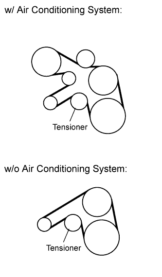
Remove the drive belt by rotating the tensioner pulley clockwise to loosen its tension with the pulley set bolt of the tensioner.
-
-
REMOVE COMPRESSOR OUTLET ELBOW
-
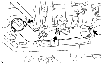
Loosen the 2 hose clamps and remove the bolt and compressor outlet elbow.
-
-
DISCONNECT COMPRESSOR ASSEMBLY WITH PULLEY (w/ Air Conditioning System)
-
Disconnect the connector.
-
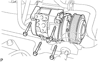
Remove the 4 bolts and compressor and magnetic clutch.
-
-
REMOVE RADIATOR HOSE INLET
-
SET NO. 1 CYLINDER TO TDC/ COMPRESSION
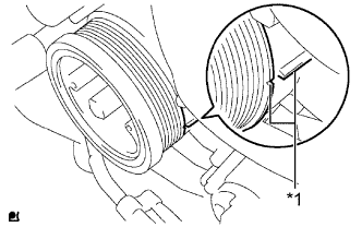
Text in Illustration *1 Matchmark
-
Align the matchmarks of the crankshaft pulley and timing gear case cover by rotating the crankshaft clockwise.
Tech Tips
Make sure that both cam lobes (intake side and exhaust side) of the No. 1 cylinder face upward.
-
-
REMOVE NO. 1 TIMING BELT COVER
-
Remove the wire harness clamp.
-
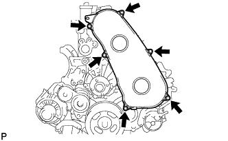
Remove the 6 bolts, 6 washers and timing belt cover.
-
-
REMOVE TIMING BELT
-
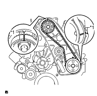
Text in Illustration *1 Timing Mark Turn the crankshaft clockwise and align the timing marks as shown in the illustration.
Tech Tips
If reusing the timing belt, place matchmarks on the timing belt so that it can be installed exactly as before.
-
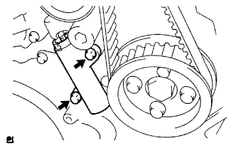
Uniformly loosen and remove the 2 bolts and No. 1 timing belt tensioner.
-
Remove the timing belt.
Tech Tips

-
If turning the camshaft while the timing belt is removed, turn the crankshaft 90° counterclockwise as shown in the illustration.
-
When installing the timing belt, turn the camshaft to align the timing marks, and then turn the crankshaft clockwise to align the timing marks.
-
-
-
REMOVE NO. 1 TIMING BELT IDLER SUB-ASSEMBLY
Note
When inspecting the No. 1 timing belt idler, do not remove it unless absolutely necessary.
-
Using a 10 mm hexagon wench, remove the bolt, No. 1 timing belt idler and washer.
-