VALVE CLEARANCE ADJUSTMENT

Note
-
When replacing the injectors (including shuffling the injectors between the cylinders), common rail or cylinder head, it is necessary to replace the injection pipes with new ones.
-
When replacing the fuel supply pump, common rail, cylinder block, cylinder head, cylinder head gasket or timing gear case, it is necessary to replace the fuel inlet pipe with a new one.
-
After removing the injection pipes, clean them with a brush and compressed air.
Tech Tips
The injectors do not need to be removed when inspecting the valve clearance.
-
REMOVE CYLINDER HEAD COVER SUB-ASSEMBLY
-
SET NO. 1 CYLINDER TO TDC/COMPRESSION
-
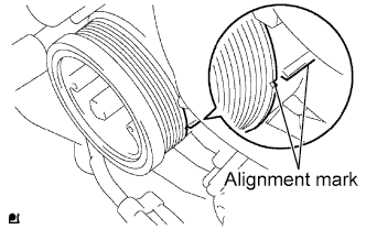
Align the alignment marks of the crankshaft pulley and timing gear case cover by rotating the crankshaft clockwise.
Tech Tips
Make sure that both cam-noses (intake side and exhaust side) of the No. 1 cylinder face upward.
-
-
INSPECT VALVE CLEARANCE
-
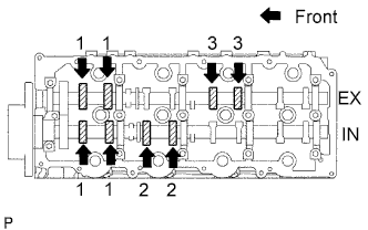
Check only the valves indicated.
-
Using a feeler gauge, measure the clearance between the valve lifter and camshaft.
Standard valve clearance (Cold) Intake Exhaust 0.20 to 0.30 mm (0.008 to 0.012 in.) 0.35 to 0.45 mm (0.014 to 0.018 in.) Write down the valve clearance measurements that are not within the specified range. These measurements will be used later to determine the size of the adjustment shim to be installed.
-
-
Turn the crankshaft 360° to set the No. 4 cylinder to TDC / compression.
-
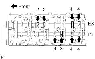
Check only the valves indicated.
-
Using a feeler gauge, measure the clearance between the valve lifter and camshaft.
Standard valve clearance Intake Exhaust 0.20 to 0.30 mm (0.008 to 0.012 in.) 0.35 to 0.45 mm (0.014 to 0.018 in.) Write down the valve clearance measurements that are not within the specified range. These measurements will be used later to determine the size of the adjustment shim to be installed.
-
-
-
ADJUST VALVE CLEARANCE
-
Remove the camshafts Click here.
-
Remove the 8 valve lifters.
-
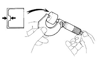
Using a micrometer, measure the thickness of the removed lifter.
-
Calculate the thickness of a new lifter so that the valve clearance comes within the specified value.
A B C New lifter thickness Used lifter thickness Measured valve clearance New lifter thickness Intake A = B + (C - 0.25 mm (0.0098 in.)) Exhaust A = B + (C - 0.40 mm (0.00158 in.)) -
Select a new lifter with a thickness as close as possible to the calculated values.
Tech Tips
Valve lifters are available in 35 sizes in increments of 0.020 mm (0.0008 in.), from 5.060 mm (0.1992 in.) to 5.740 mm (0.2260 in.).
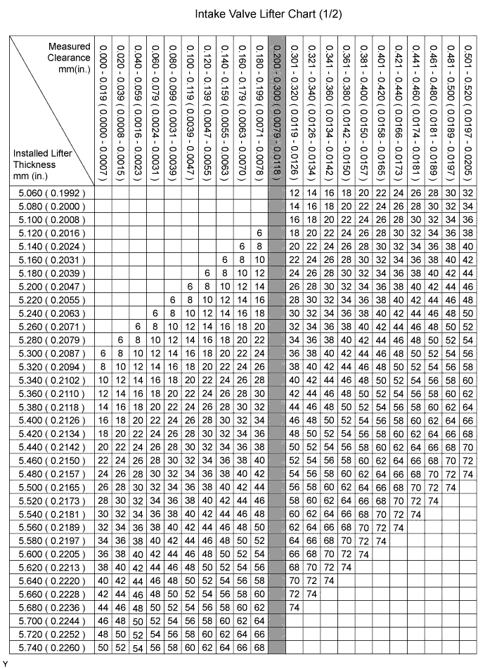
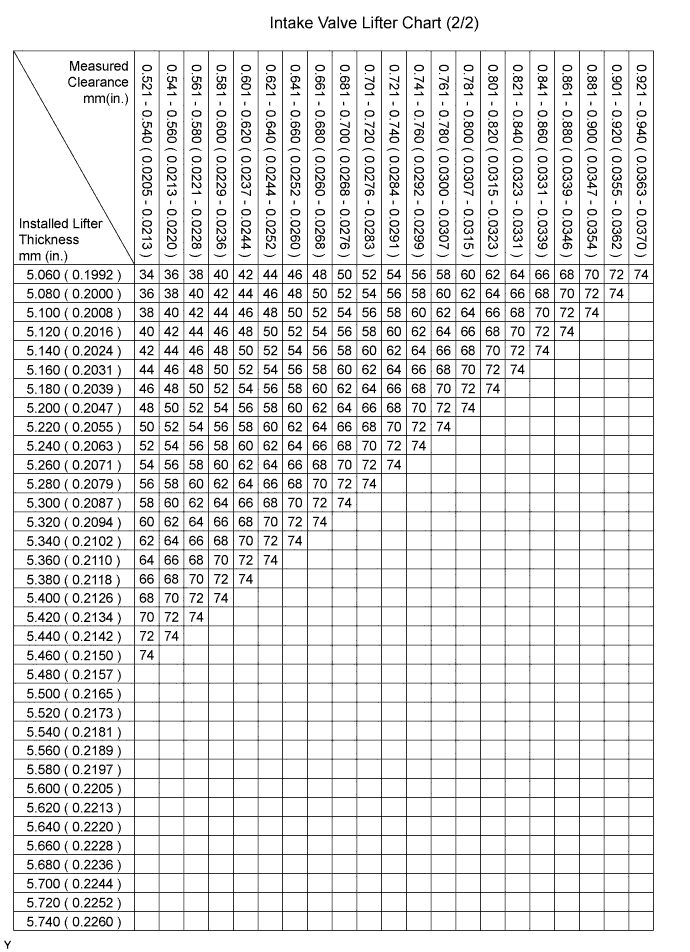
Standard intake valve clearance (Cold) 0.20 to 0.30 mm (0.008 to 0.012 in.) EXAMPLE The 5.250 mm (0.2067 in.) lifter is installed, and the measured clearance is 0.400 mm (0.0158 in.). Replace the 5.250 mm (0.2067 in.) shim with a No. 40 lifter. New lifter thickness (mm (in.)) Shim No. Thickness Shim No. Thickness Shim No. Thickness 06 5.060 (0.1992) 30 5.300 (0.2087) 54 5.540 (0.2181) 08 5.080 (0.2000) 32 5.320 (0.2094) 56 5.560 (0.2189) 10 5.100 (0.2008) 34 5.340 (0.2102) 58 5.580 (0.2197) 12 5.120 (0.2016) 36 5.360 (0.2110) 60 5.600 (0.2205) 14 5.140 (0.2024) 38 5.380 (0.2118) 62 5.620 (0.2213) 16 5.160 (0.2031) 40 5.400 (0.2126) 64 5.640 (0.2220) 18 5.180 (0.2039) 42 5.420 (0.2134) 66 5.660 (0.2228) 20 5.200 (0.2047) 44 5.440 (0.2142) 68 5.680 (0.2236) 22 5.220 (0.2055) 46 5.460 (0.2150) 70 5.700 (0.2244) 24 5.240 (0.2063) 48 5.480 (0.2157) 72 5.720 (0.2252) 26 5.260 (0.2071) 50 5.500 (0.2165) 74 5.740 (0.2260) 28 5.280 (0.2079) 52 5.520 (0.2173) - - 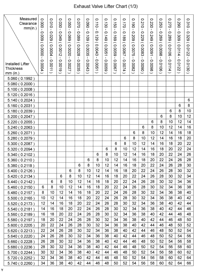
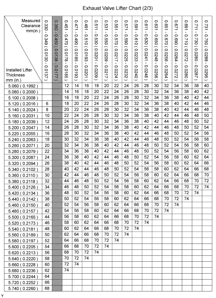
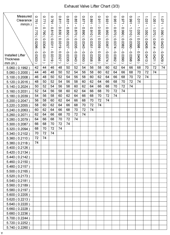
Standard exhaust valve clearance (Cold) 0.35 to 0.45 mm (0.014 to 0.018 in.) EXAMPLE The 5.340 mm (0.2102 in.) lifter is installed, and the measured clearance is 0.480 mm (0.0189 in.). Replace the 5.340 mm (0.2102 in.) shim with a No. 42 lifter. New lifter thickness (mm (in.)) Shim No. Thickness Shim No. Thickness Shim No. Thickness 06 5.060 (0.1992) 30 5.300 (0.2087) 54 5.540 (0.2181) 08 5.080 (0.2000) 32 5.320 (0.2094) 56 5.560 (0.2189) 10 5.100 (0.2008) 34 5.340 (0.2102) 58 5.580 (0.2197) 12 5.120 (0.2016) 36 5.360 (0.2110) 60 5.600 (0.2205) 14 5.140 (0.2024) 38 5.380 (0.2118) 62 5.620 (0.2213) 16 5.160 (0.2031) 40 5.400 (0.2126) 64 5.640 (0.2220) 18 5.180 (0.2039) 42 5.420 (0.2134) 66 5.660 (0.2228) 20 5.200 (0.2047) 44 5.440 (0.2142) 68 5.680 (0.2236) 22 5.220 (0.2055) 46 5.460 (0.2150) 70 5.700 (0.2244) 24 5.240 (0.2063) 48 5.480 (0.2157) 72 5.720 (0.2252) 26 5.260 (0.2071) 50 5.500 (0.2165) 74 5.740 (0.2260) 28 5.280 (0.2079) 52 5.520 (0.2173) - - -
Install the selected valve lifters.
-
Install the camshafts Click here.
-
-
INSTALL CYLINDER HEAD COVER SUB-ASSEMBLY