ENGINE ASSEMBLY (w/ DPF) INSTALLATION

Note
-
When replacing the injectors (including shuffling the injectors between the cylinders), common rail or cylinder head, it is necessary to replace the injection pipes with new ones.
-
When replacing the fuel supply pump, common rail, cylinder block, cylinder head, cylinder head gasket or timing gear case, it is necessary to replace the fuel inlet pipe with a new one.
-
After removing the injection pipes, clean them with a brush and compressed air.
-
INSTALL FRONT NO. 1 ENGINE MOUNTING BRACKET LH
-
Install the front No. 1 engine mounting bracket LH with the 4 bolts.
- Torque:
- 68 N*m { 693 kgf*cm, 50 ft.*lbf }
-
-
INSTALL FRONT NO. 1 ENGINE MOUNTING BRACKET RH
-
Install the front No. 1 engine mounting bracket RH with the 4 bolts.
- Torque:
- 68 N*m { 693 kgf*cm, 50 ft.*lbf }
-
-
INSTALL OIL COOLER COVER SUB-ASSEMBLY
-
INSTALL NO. 2 VACUUM TRANSMITTING PIPE SUB-ASSEMBLY
-
Install the No. 2 vacuum transmitting pipe with the bolt and 2 nuts.
- Torque:
- 13 N*m { 133 kgf*cm, 10 ft.*lbf }
-
-
INSTALL NO. 1 VACUUM TRANSMITTING PIPE SUB-ASSEMBLY
-
Install the No. 1 vacuum transmitting pipe with the bolt and nut.
- Torque:
- for bolt
- 13 N*m { 133 kgf*cm, 10 ft.*lbf }
- for nut
- 8.0 N*m { 82 kgf*cm, 71 in.*lbf }
-
Connect the vacuum hose.
-
-
INSTALL NO. 3 FUEL PIPE
-
INSTALL WATER OUTLET
-
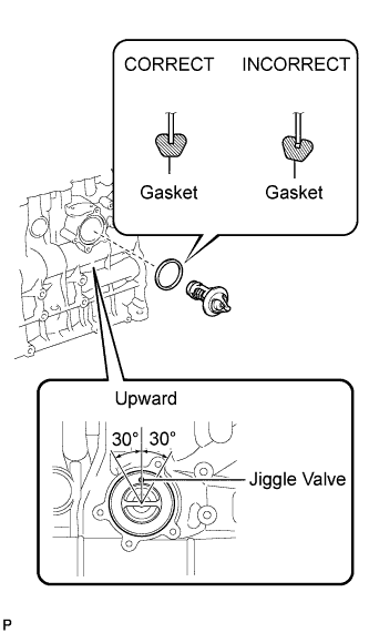
Text in Illustration *1 Claw Install a new gasket to the cylinder head as shown in the illustration.
Tech Tips
Make sure the claws of the gasket face the water outlet.
-
Install the water outlet with the 2 bolts.
- Torque:
- 19 N*m { 194 kgf*cm, 14 ft.*lbf }
-
-
INSTALL SWIRL CONTROL VALVE ASSEMBLY
-
Temporarily install a new gasket and the swirl control valve with the 4 bolts and 2 nuts.
Note
Make sure that the swirl control valve actuator is not damaged by the surrounding parts.
-
Tighten the 4 bolts and 2 nuts in the order shown in the illustration.
- Torque:
- 29 N*m { 296 kgf*cm, 21 ft.*lbf }
-
-
INSTALL VACUUM SWITCHING VALVE SET
-
Install the vacuum control valve set with the 2 bolts.
- Torque:
- 20 N*m { 204 kgf*cm, 15 ft.*lbf }
-
Connect the 3 vacuum hoses and 2 connectors.
Tech Tips
When connecting the hoses, match the color of the paint mark on the hoses to the color of the paint mark on the swirl control valve as shown in the illustration.
-
-
INSTALL INTAKE MANIFOLD
-
Temporarily install a new gasket and the intake manifold with the 7 bolts and 2 nuts.
-
Tighten the 7 bolts and 2 nuts in the order shown in the illustration.
- Torque:
- 20 N*m { 204 kgf*cm, 15 ft.*lbf }
-
Connect the vacuum hoses.
-
-
INSTALL NO. 1 INTAKE MANIFOLD INSULATOR
-
Install the No. 1 intake manifold insulator to the intake manifold.
-
-
INSTALL INTAKE MANIFOLD STAY
-
Install the manifold stay with the 2 bolts.
- Torque:
- 19 N*m { 194 kgf*cm, 14 ft.*lbf }
-
-
INSTALL NO. 2 CYLINDER BLOCK INSULATOR
-
INSTALL THERMOSTAT
-
Install a new gasket onto the thermostat.
Tech Tips
When installing the thermostat onto the gasket, be careful not to deform the gasket. Make sure that the thermostat is properly installed into the groove of the gasket as shown in the illustration.
-
Insert the thermostat into the cylinder block with the jiggle valve facing straight upward.
Tech Tips
The jiggle valve may be set within 30° on either side of the prescribed position.
-
-
INSTALL WATER INLET
-
Install the water inlet with the 3 bolts.
- Torque:
- 13 N*m { 133 kgf*cm, 10 ft.*lbf }
-
-
INSTALL NO. 2 WATER BY-PASS PIPE
-
Temporarily install a new gasket and the No. 2 water by-pass pipe with the bolt and nut.
-
Tighten the bolt and nut in the order shown in the illustration.
- Torque:
- for bolt
- 23 N*m { 235 kgf*cm, 17 ft.*lbf }
- for nut
- 10 N*m { 102 kgf*cm, 7 ft.*lbf }
-
-
INSTALL NO. 5 WATER BY-PASS PIPE SUB-ASSEMBLY
-
Temporarily install the No. 5 water by-pass pipe with the 2 bolts and nut.
-
Tighten the 2 bolts and nut in the order shown in the illustration.
- Torque:
- 10 N*m { 102 kgf*cm, 7 ft.*lbf }
-
Connect the water hose to the No. 2 water by-pass pipe.
-
-
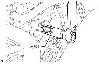
INSTALL CRANKSHAFT PULLEY
-
Align the keyway of the pulley with the key located on the crankshaft, and then slide the pulley into place to install it.
-
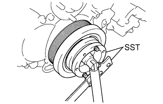
Using SST, install the pulley bolt.
- SST
- 09213-58014
- 09330-00021
- Torque:
- 365 N*m { 3722 kgf*cm, 269 ft.*lbf }
-
-
INSTALL FUEL SUPPLY PUMP ASSEMBLY
-
INSTALL GLOW PLUG ASSEMBLY
-
INSTALL EGR COOLER ASSEMBLY
-
INSTALL ELECTRIC EGR CONTROL VALVE ASSEMBLY
-
INSTALL COMMON RAIL ASSEMBLY
-
INSTALL DIESEL THROTTLE BODY ASSEMBLY
-
Install a new gasket and the diesel throttle body with the 2 bolts and 2 nuts.
- Torque:
- 20 N*m { 204 kgf*cm, 15 ft.*lbf }
-
Connect the 2 diesel throttle body connectors.
-
w/o DPF:
-
Install the wire harness clamp with the bolt.
- Torque:
- 9.0 N*m { 92 kgf*cm, 80 in.*lbf }
-
Connect the diesel turbo pressure sensor connector and vacuum switching valve connector.
-
-
-
INSTALL OIL PRESSURE SWITCHING VALVE ASSEMBLY
-
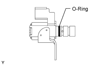
Apply a light coat of engine oil to the O-ring of the oil pressure switching valve.
-
Install the oil pressure switching valve with the bolt.
- Torque:
- 10 N*m { 102 kgf*cm, 7 ft.*lbf }
Note
Make sure that the O-ring is not cracked or jammed when installing the oil pressure switching valve.
-
Connect the oil pressure switching valve connector.
-
-
INSTALL CAMSHAFT POSITION SENSOR
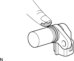
-
Apply a light coat of engine oil to the O-ring of the camshaft position sensor.
-
Install the camshaft position sensor with the bolt.
- Torque:
- 8.5 N*m { 87 kgf*cm, 75 in.*lbf }
Note
Do not crack or jam the O-ring when installing the camshaft position sensor.
-
Connect the camshaft position sensor connector.
-
-
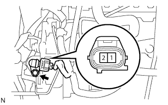
INSTALL CRANKSHAFT POSITION SENSOR
-
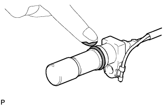
Apply a light coat of engine oil to the O-ring of the crankshaft position sensor.
-
TYPE A:
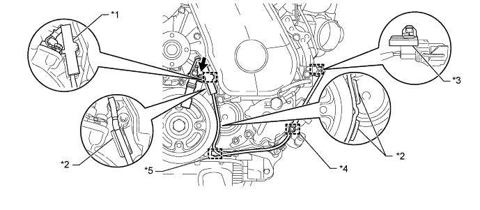
Text in Illustration *1 Clamp *2 Protrusion *3 Wire Harness Clamp (A) *4 Wire Harness Clamp (B) *5 Wire Harness Clamp (C) - -
-
Install the wire harness clamp (A) to the crankshaft position sensor connector.
-
Install the crankshaft position sensor with the bolt.
- Torque:
- 8.5 N*m { 87 kgf*cm, 75 in.*lbf }
Note
Make sure that the O-ring is not damaged or does not jump out of position during installation.
-
Install a new clamp.
Note
-
Make sure that no portion of the clamp remains in the clamp installation hole. If there is any portion of the clamp remaining, remove it.
-
Make sure the crankshaft position sensor wire harness is installed in the position shown in the illustration.
-
-
Attach the crankshaft position sensor connector to the No. 1 vacuum transmitting pipe.
-
Connect the crankshaft position sensor connector.
-
Attach the 2 wire harness clamps (B, C).
-
-
TYPE B:
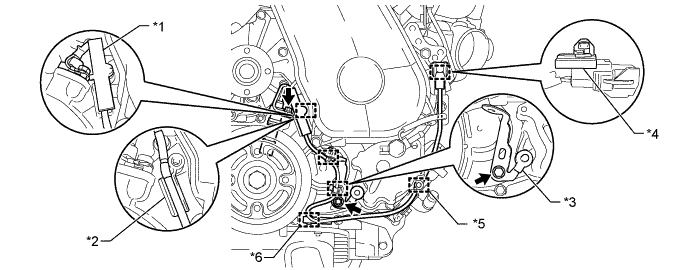
Text in Illustration *1 Clamp *2 Protrusion *3 Bracket (Clamp) *4 Wire Harness Clamp (A) *5 Wire Harness Clamp (B) *6 Wire Harness Clamp (C)
-
Install the wire harness clamp (A) to the crankshaft position sensor connector.
-
Install the crankshaft position sensor with the bolt.
- Torque:
- 8.5 N*m { 87 kgf*cm, 75 in.*lbf }
Note
Make sure that the O-ring is not damaged or does not jump out of position during installation.
-
Install the bracket (clamp) with the bolt.
- Torque:
- 13 N*m { 132 kgf*cm, 9.5 ft.*lbf }
-
Install a new clamp.
Note
-
Make sure that no portion of the clamp remains in the clamp installation hole. If there is any portion of the clamp remaining, remove it.
-
Make sure the crankshaft position sensor wire harness is installed in the position shown in the illustration.
-
-
Attach the crankshaft position sensor connector to the No. 1 vacuum transmitting pipe.
-
Connect the crankshaft position sensor connector.
-
Attach the 2 wire harness clamps (B, C).
-
Attach the 2 wire harness clamps to the bracket (clamp).
-
-
-
INSTALL ENGINE COOLANT TEMPERATURE SENSOR
-
Install a new gasket onto the engine coolant temperature sensor.
-
Using SST, install the engine coolant temperature sensor.
- SST
- 09817-33190
- Torque:
- 20 N*m { 200 kgf*cm, 14 ft.*lbf }
-
Connect the engine coolant temperature sensor connector.
-
-
INSTALL NO. 1 TIMING BELT IDLER SUB-ASSEMBLY
-
Using a 10 mm hexagon wrench, install a new washer and the No. 1 timing belt idler with the bolt.
- Torque:
- 35 N*m { 357 kgf*cm, 26 ft.*lbf }
-
-
INSTALL TIMING BELT
-
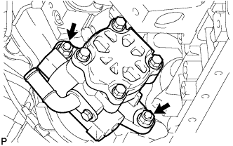
INSTALL VACUUM PUMP ASSEMBLY
-
Install 2 new O-rings and the vacuum pump with the 2 nuts.
- Torque:
- 21 N*m { 210 kgf*cm, 15 ft.*lbf }
-
-
INSTALL VANE PUMP ASSEMBLY
-
Install a new vane pump O-ring to the vane pump assembly.
-
Install the vane pump assembly with the 2 nuts.
- Torque:
- 39 N*m { 398 kgf*cm, 29 ft.*lbf }
Note
Make sure that the vane pump O-ring is not caught between other parts.
-
-
INSTALL ENGINE WIRE
-
Install the engine wire to the engine.
-
-
INSTALL ENGINE HANGERS
-
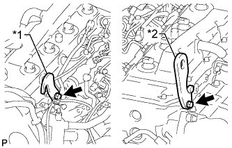
Text in Illustration *1 Upper No. 1 Engine Hanger *2 No. 2 Engine Hanger Install a No. 1 engine hanger and No. 2 engine hanger with 2 bolts as shown in the illustration.
- Torque:
- for upper No. 1 engine hanger
- 25 N*m { 255 kgf*cm }
- for No. 2 engine hanger
- 60 N*m { 612 kgf*cm }
Note
Install the engine hangers with new bolts.
Tech Tips
Upper No. 1 Engine Hanger 12284-30020 No. 2 Engine Hanger 12282-67030 Bolt 91552-81025 and 91642-81030 -
Attach an engine sling device and hang the engine with a chain block.
-
-
REMOVE ENGINE STAND
-
Remove the engine from the engine stand.
-
-
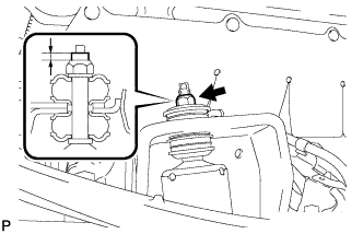
INSTALL FRONT ENGINE MOUNTING INSULATOR
-
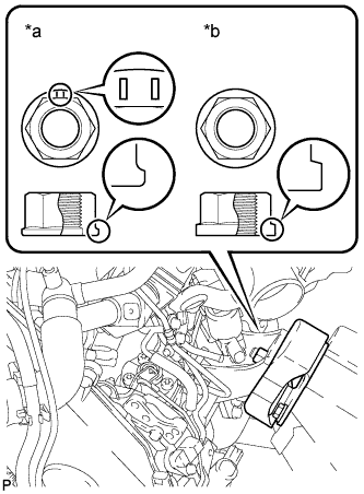
Text in Illustration *a Nut Type A *b Nut Type B Install the 2 front engine mounting insulators and 2 engine mounting stabilizers with the 2 nuts.
- Torque:
- for nut type A
- 76 N*m { 755 kgf*cm, 56 ft.*lbf }
- for nut type B
- 48 N*m { 489 kgf*cm, 35 ft.*lbf }
-
-
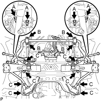
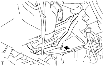
INSTALL FRONT SUSPENSION CROSSMEMBER SUB-ASSEMBLY
-
Install the front suspension crossmember with the 4 bolts.
- Torque:
- 55 N*m { 561 kgf*cm, 41 ft.*lbf }
-
-
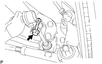
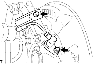
CONNECT PRESSURE FEED TUBE ASSEMBLY
-
Install a new gasket to the pressure feed tube assembly.
-
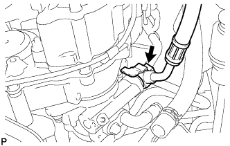
Connect the pressure feed tube assembly to the vane pump assembly with the union bolt.
- Torque:
- 50 N*m { 510 kgf*cm, 37 ft.*lbf }
Tech Tips
Make sure the stopper of the pressure feed tube assembly contacts the vane pump assembly as shown in the illustration.
-
-
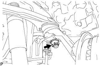
CONNECT NO. 1 OIL RESERVOIR TO PUMP HOSE
-
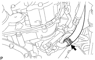
Connect the No.1 oil reservoir to pump hose to the vane pump assembly with the clip.
-
-
INSTALL ENGINE ASSEMBLY
-
Set an engine lifter in place.
-
Remove the engine sling device and chain block.
-
Remove the 2 bolts and 2 engine hangers.
-
Operate the engine lifter and install the engine to the vehicle.
-
Install the engine with crossmember with the 16 bolts.
- Torque:
- for bolt A
- 39 N*m { 398 kgf*cm, 29 ft.*lbf }
- for bolt B
- 36 N*m { 367 kgf*cm, 27 ft.*lbf }
- for bolt C
- 150 N*m { 1530 kgf*cm, 111 ft.*lbf }
-
Remove the engine lifter.
-
-
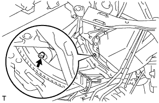
CONNECT STEERING TORQUE SHAFT ASSEMBLY
-
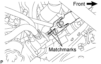
Align the matchmarks on the steering torque shaft assembly and the power steering link assembly.
-
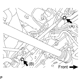
Install bolt (B) and tighten the 2 bolts.
- Torque:
- 35 N*m { 360 kgf*cm, 26 ft.*lbf }
-
-
TEMPORARILY INSTALL FRONT SHOCK ABSORBER ASSEMBLY LH
-
Install front shock absorber No.1 cushion retainer, front shock absorber No.2 cushion retainer, and the front shock absorber cushion to the front shock absorber.
Note
Install the cushion retainers in the correct direction.
-
Install the front shock absorber, front shock absorber No.1 cushion retainer , front shock absorber No.2 cushion retainer, and the front shock absorber cushion to the vehicle, and temporarily tighten a new lock nut.
Note
Install the cushion retainers in the correct direction.
-
Hold the width across flat of the piston rod and tighten the lock nut with an adjustable wrench until the protrusion length of the thread is the standard length.
Standard 3 +- 1 mm (0.12 +- 0.04 in.) -
Install the front shock absorber to the front suspension lower arm. Insert the bolt from the front side of the vehicle and temporarily tighten the bolt.
-
-
TEMPORARILY INSTALL FRONT SHOCK ABSORBER ASSEMBLY RH
Tech Tips
Use the same procedure described for the LH side.
-
CONNECT FRONT SUSPENSION ARM SUB-ASSEMBLY UPPER LH
-
Connect the front suspension upper arm to the steering knuckle with the nut.
- Torque:
- 113 N*m { 1,150 kgf*cm, 83 ft.*lbf }
-
Install a new cotter pin.
Note
-
If the holes for the cotter pin are not aligned, tighten the nut up to 60°.
-
Do not damage the ball joint dust cover.
-
-
-
CONNECT FRONT SUSPENSION ARM SUB-ASSEMBLY UPPER RH
Tech Tips
Use the same procedure described for the LH side.
-
CONNECT FRONT DISC BRAKE CALIPER ASSEMBLY LH
-
Install the brake caliper assembly to the steering knuckle with the 2 bolts.
- Torque:
- 123 N*m { 1,250 kgf*cm, 91 ft.*lbf }
-
-
CONNECT FRONT DISC BRAKE CALIPER ASSEMBLY RH
Tech Tips
Use the same procedure described for the LH side.
-
CONNECT FRONT SPEED SENSOR LH
-
Install the speed sensor to the steering knuckle with the 2 bolts.
- Torque:
- 8.5 N*m { 87 kgf*cm, 75 in.*lbf }
Note
-
Prevent foreign matter from adhering to the speed sensor.
-
Be careful not to damage the speed sensor.
-
Do not twist the sensor wire when installing the speed sensor.
-
-
CONNECT FRONT SPEED SENSOR RH
Tech Tips
Use the same procedure described for the LH side.
-
INSTALL REAR END PLATE
-
Install the rear end plate with the bolt.
- Torque:
- 8.0 N*m { 82 kgf*cm, 71 in.*lbf }
-
-
INSTALL FLYWHEEL SUB-ASSEMBLY (for Manual Transmission)
-
Clean the bolts and their holes.
-
Apply adhesive to 2 or 3 threads at the end of each bolt.
Adhesive Toyota Genuine Adhesive 1324, Three Bond 1324 or equivalent -
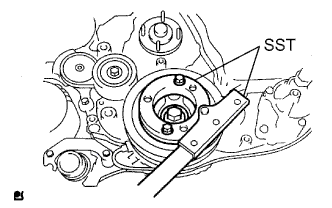
Using SST, hold the crankshaft pulley.
- SST
- 09213-58014
- 09330-00021
-
Install the flywheel to the crankshaft.
-
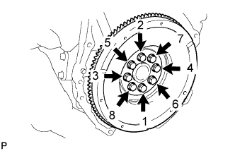
Install and uniformly tighten the 8 bolts in the sequence shown in the illustration.
- Torque:
- 178 N*m { 1815 kgf*cm, 131 ft.*lbf }
Note
Do not start the engine for at least 1 hour after installation.
-
-
INSTALL PUMP IMPELLER DRIVE PLATE (for Automatic Transmission)
-
Clean the bolts and their holes.
-
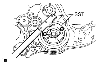
Using SST, hold the crankshaft pulley.
- SST
- 09213-58014
- 09330-00021
-
Text in Illustration *a Engine Side Install the flywheel, pump impeller drive plate and rear drive plate spacer to the crankshaft.
Note
Align either hole in the pump impeller drive plate and either hole in the rear drive plate spacer with the knock pin of the flywheel, and then install the flywheel and ring gear, the pump impeller drive plate, and the rear drive plate spacer to the crankshaft.
Tech Tips
As the rear drive plate spacer and pump impeller drive plate are not reversible, be sure to install them in the direction shown in the illustration.
-
Install and uniformly tighten the 8 bolts in several steps in the sequence shown in the illustration.
- Torque:
- 178 N*m { 1815 kgf*cm, 131 ft.*lbf }
Note
Do not start the engine for at least an hour after installing the flywheel and ring gear.
-
-
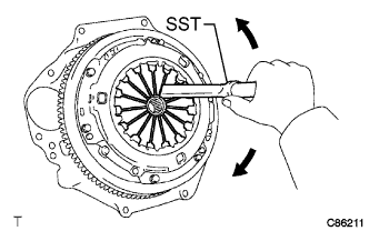
INSTALL CLUTCH DISC ASSEMBLY (for Manual Transmission)
-
Insert SST into the clutch disc assembly, then insert them into the flywheel sub-assembly.
- SST
- 09301-00110
Note
Take care not to insert the clutch disc assembly in the wrong direction.
-
-
INSTALL CLUTCH COVER ASSEMBLY (for Manual Transmission)
-
Align the matchmarks on the clutch cover assembly with the one on the flywheel sub-assembly.
-
Following the procedures shown in the illustration, tighten the 6 bolts starting from the bolt located near the knock pin on the top.
- SST
- 09301-00110
- Torque:
- 19 N*m { 195 kgf*cm, 14 ft.*lbf }
Tech Tips
-
Evenly tighten the bolts by following the order shown in the illustration.
-
Tighten the bolts after checking that the disc is in the center by lightly moving the SST up and down, left and right.
-
-
INSPECT AND ADJUST CLUTCH COVER ASSEMBLY (for Manual Transmission)
-
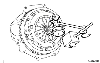
Using a dial indicator with a roller instrument, check the diaphragm spring tip alignment.
Maximum non-alignment 1.3 mm (0.051 in.) -
If alignment is not as specified, adjust the diaphragm spring tip alignment using SST.
- SST
- 09333-00013
-
-
INSTALL AUTOMATIC TRANSMISSION ASSEMBLY (for Automatic Transmission)
-
INSTALL DRIVE PLATE AND TORQUE CONVERTER CLUTCH SETTING BOLT (for Automatic Transmission)
-
Turn the crankshaft pulley and install the 6 drive plate and torque converter clutch setting bolts.
- Torque:
- 48 N*m { 490 kgf*cm, 36 ft.*lbf }
Tech Tips
First install the black colored bolt, and then the remaining 5 bolts.
-
Install the drive plate cover onto the automatic transmission assembly with the bolt.
- Torque:
- 73 N*m { 744 kgf*cm, 54 ft.*lbf }
-
-
INSTALL MANUAL TRANSMISSION ASSEMBLY (for Manual Transmission)
-
INSTALL PROPELLER SHAFT ASSEMBLY
-
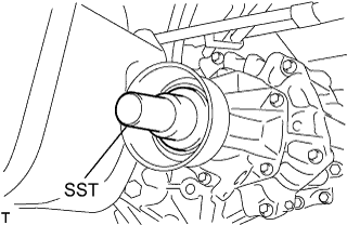
Remove the SST from the extension housing.
-
Install the propeller shaft assembly in the extension housing.
-
Align the matchmarks on the propeller shaft flange and differential flange.
-
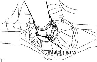
Install the propeller shaft assembly with the 4 nuts, 4 bolts and 4 washers.
- Torque:
- 74 N*m { 755 kgf*cm, 54 ft.*lbf }
-
-
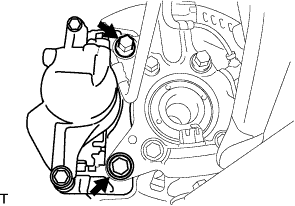
CONNECT VANE PUMP OIL RESERVOIR ASSEMBLY
-
Connect the vane pump oil reservoir with the 2 bolts.
- Torque:
- 8.0 N*m { 82 kgf*cm, 71 in.*lbf }
-
-
CONNECT ENGINE ROOM MAIN WIRE
-
Install the nut and close the cover.
- Torque:
- 8.2 N*m { 84 kgf*cm, 73 in.*lbf }
-
Connect the 5 connectors.
-
Attach the clamp and connect the engine room main wire.
-
-
CONNECT ENGINE WIRE
-
Connect the 4 ECM connectors.
-
Attach the 3 clips and install the wire harness support.
-
Install the bolt.
- Torque:
- 9.0 N*m { 92 kgf*cm, 80 in.*lbf }
-
Connect the 4 connectors and engine wire.
-
-
CONNECT VACUUM HOSE
-
Connect the vacuum hose to the vacuum pump.
-
-
CONNECT NO. 1 FUEL HOSE
-
Connect the No. 1 fuel hose to the fuel supply pump.
-
-
CONNECT NO. 2 FUEL HOSE
-
Connect the No. 2 fuel hose to the No. 3 nozzle leakage pipe.
-
-
CONNECT NO. 4 RADIATOR HOSE
-
Connect the No. 4 radiator hose to the water outlet.
-
-
INSTALL NO. 4 AIR HOSE
-
Install the No. 4 air hose and tighten the 2 hose clamps.
- Torque:
- 6.0 N*m { 61 kgf*cm, 53 in.*lbf }
-
-
CONNECT OIL RETURN HOSE
-
Attach the 2 clamps and connect the oil return hose to the intake manifold.
-
-
CONNECT NO. 3 WATER BY-PASS HOSE
-
Attach the clamp and connect the No. 3 by-pass hose to the No. 2 water by-pass pipe.
-
-
CONNECT HEATER HOSE
-
Connect the heater hose to the No. 2 water by-pass pipe.
-
-
CONNECT NO. 1 RADIATOR HOSE
-
Connect the No. 1 radiator hose to the water inlet.
-
-
INSTALL V-RIBBED BELT TENSIONER ASSEMBLY
-
Temporarily install the V-ribbed belt tensioner with the 4 bolts.
-
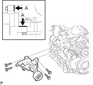
Tighten the 4 bolts.
- Torque:
- 21 N*m { 214 kgf*cm, 15 ft.*lbf }
Tech Tips
Firmly press and hold the V-ribbed belt tensioner against the cylinder block to eliminate any gaps in the areas labeled A in the illustration. Then uniformly tighten the 4 bolts.
-
-
INSTALL NO. 1 COMPRESSOR MOUNTING BRACKET
-
Temporarily install the No. 1 compressor mounting bracket with the 4 bolts.
-
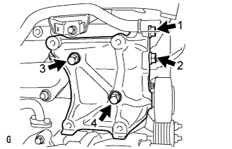
Tighten the 4 bolts in the order shown in the illustration.
- Torque:
- 45 N*m { 459 kgf*cm, 33 ft.*lbf }
Tech Tips
Make sure that the No. 1 compressor mounting bracket is in contact with the cylinder block.
-
-
INSTALL EXHAUST MANIFOLD
-
Set a new gasket on the cylinder head.
-
Install the exhaust manifold, 8 collars and 8 plate washers with 8 new nuts.
- Torque:
- 40 N*m { 408 kgf*cm, 30 ft.*lbf }
Note
Install the collars so that the side with the smaller external diameter faces the exhaust manifold.
-
-
INSTALL TURBOCHARGER SUB-ASSEMBLY
-
INSTALL FRONT EXHAUST PIPE ASSEMBLY
-
INSTALL GENERATOR ASSEMBLY
-
INSTALL TRANSMISSION OIL LEVEL GAGE SUB-ASSEMBLY (for Automatic Transmission)
-
INSTALL FRONT WHEELS
- Torque:
- 100 N*m { 1,020 kgf*cm, 74 ft.*lbf }
-
TIGHTEN FRONT SHOCK ABSORBER ASSEMBLY LH
-
Tighten the bolt on the lower side of the front shock absorber.
- Torque:
- 105 N*m { 1,070 kgf*cm, 77 ft.*lbf }
-
-
TIGHTEN FRONT SHOCK ABSORBER ASSEMBLY RH
Tech Tips
Use the same procedure described for the LH side.
-
CONNECT CABLE TO NEGATIVE BATTERY TERMINAL
-
PERFORM REGISTRATION
-
Perform registration of the injector compensation codes Click here.
-
-
BLEED AIR FROM FUEL SYSTEM
-
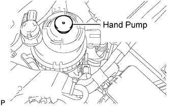
Using the hand pump mounted on the fuel filter cap, bleed air from the fuel system. Continue pumping until the pump resistance increases.
Note
-
Hand pump pumping speed: Max. 2 strokes/ sec.
-
The hand pump must be pushed with a full stroke during pumping.
-
When the fuel pressure at the supply pump inlet port reaches a saturated pressure, the hand pump resistance increases.
-
If pumping is interrupted during the air bleeding process, fuel in the fuel line may return to the fuel tank. Continue pumping until the hand pump resistance increases.
-
If the hand pump resistance does not increase despite consecutively pumping 200 times or more, there may be a fuel leak between the fuel tank and fuel filter, the hand pump may be malfunctioning, or the vehicle may have run out of fuel.
-
If air bleeding using the hand pump is incomplete, the common rail pressure does not rise to the pressure range necessary for normal use, and the engine cannot be started.
-
-
Check if the engine starts.
Note
-
Even if air bleeding using the hand pump has been completed, the starter may need to be cranked for 10 seconds or more to start the engine.
-
Do not crank the engine continuously for more than 20 seconds. The battery may be discharged.
-
Use a fully-charged battery.
-
When the engine can be started, proceed to the next step.
-
If the engine cannot be started, bleed air again using the hand pump until the hand pump resistance increases (refer to the procedures above). Then start the engine.
-
-
Turn the ignition switch off.
-
Connect the intelligent tester to the DLC3.
-
Turn the ignition switch to ON and turn the intelligent tester on.
-
Clear the DTCs.
-
w/ DPF: Click here
-
w/o DPF: Click here
-
-
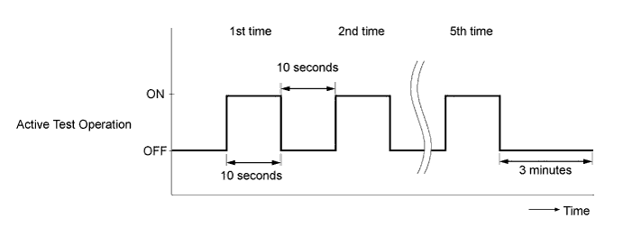
Start the engine.*1
-
Enter the following menus: Powertrain / Engine and ECT / Active Test / Test the Fuel Leak.*2
-
Perform the following test 5 times with on/off intervals of 10 seconds: Active Test / Test the Fuel Leak.*3
-
Allow the engine to idle for 3 minutes or more after performing the Active Test for the fifth time.
Tech Tips
When the Active Test "Test the Fuel Leak" is used to change the pump control mode, the actual fuel pressure inside the common rail drops below the target fuel pressure when the Active Test is off, but this is normal and does not indicate a pump malfunction.
-
Enter the following menus: Powertrain / Engine and ECT / DTC.
-
Read Current DTCs.
-
Clear the DTCs.
-
w/ DPF: Click here
-
w/o DPF: Click here
Tech Tips
It is necessary to clear the DTCs as DTC P1604 or P1605 may be stored when air is bled from the fuel system after replacing or repairing fuel system parts.
-
-
Repeat steps *1 to *3.
-
Enter the following menus: Powertrain / Engine and ECT / DTC.
-
Read Current DTCs.
OK No DTCs are output.
-
-
CHARGE REFRIGERANT
-
Perform vacuum purging using a vacuum pump.
-
Charge with refrigerant HFC-134a (R134a).
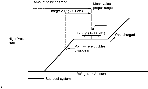
Standard Single A/C 520 to 580g (18.3 to 20.5 oz.) Dual A/C 670 to 730g (23.0 to 25.7 oz.) - SST
- 07110-58060 ( 07117-58090, 07117-78050, 07117-58070, 07117-58060, 07117-58080, 07117-88060, 07117-88070, 07117-88080 )
Note
-
Do not operate the cooler compressor before charging refrigerant as the cooler compressor does not work properly without any refrigerant, which causes the compressor to overheat.
-
Approximately 100 g (3.5 oz.) of refrigerant may need to be charged after bubbles disappear. The refrigerant amount should be checked by quantity, and not with the sight glass.
Tech Tips
Prepare a service can to recharge refrigerant if using the refrigerant gas collected with the freon collection/recycling device because the collective rate of the device is approximately 90%.
-
-
ADD ENGINE OIL
-
Add new engine oil.
Standard Oil Grade Item Oil Grade Oil Viscosity (SAE) w/ DPF ACEA C2
(Using engine oil other than ACEA C2 may damage catalytic converter)
- 0W-30
- 5W-30
w/o DPF G-DLD1, API CF-4, CF or ACEA B1
(You may also use API CE or CD)
- 5W-30
- 10W-30
- 15W-40
- 20W-50
Standard Capacity (w/ DPF) Item Fill Amount Drain and refill without oil filter change 6.6 liters (7.0 US qts, 5.8 Imp. qts) Drain and refill with oil filter change 6.8 liters (7.2 US qts, 6.0 Imp. qts) Dry fill 7.5 liters (7.9 US qts, 6.6 Imp. qts) Standard Capacity (w/o DPF) Item Fill Amount Drain and refill without oil filter change 6.8 liters (7.2 US qts, 6.0 Imp. qts) Drain and refill with oil filter change 7.0 liters (7.4 US qts, 6.2 Imp. qts) Dry fill 7.7 liters (8.1 US qts, 6.8 Imp. qts) -
Install the oil filler cap.
-
-
ADD ENGINE COOLANT
-
Firmly tighten the drain plugs.
-
Fill the radiator reservoir with coolant to the top of the inlet.
Standard Capacity Item Specified Condition w/o Heater 13.6 liters (14.4 US qts, 12.0 Imp. qts) w/ Front Heater 14.6 liters (15.4 US qts, 12.8 Imp. qts) w/ Front and Rear Heaters 16.6 liters (17.5 US qts, 14.6 Imp. qts) Note
Do not substitute plain water for engine coolant.
Tech Tips
-
Use of improper coolants may damage the engine cooling system.
-
Use only Toyota Super Long Life Coolant or similar high quality ethylene glycol based non-silicate, non-amine, non-nitrite, and non-borate coolant with long-life hybrid organic acid technology (coolant with long-life hybrid organic acid technology consists of a combination of low phosphates and organic acids).
-
-
Loosen the bleeder plug of the outlet housing.
-
When air is bled and the coolant drains out, firmly tighten the bleeder plug.
- Torque:
- 8.0 N*m { 82 kgf*cm, 71 in.*lbf }
-

Add coolant up to the B line mark in the radiator reservoir and install the reservoir cap.
-
Warm up the engine until the thermostat opens.
-
While the thermostat is open, circulate the coolant for several minutes.
Tech Tips
The thermostat open timing can be confirmed by pressing the inlet radiator hose by hand, and checking when the engine coolant starts to flow inside the hose.
-
-

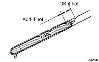
After the engine cools down, check that the coolant level is between the LOW and FULL level marks.
-
-
ADD POWER STEERING FLUID
-
ADD MANUAL TRANSMISSION OIL (for Manual Transmission)
-
Park the vehicle in a level place.
-
Remove the transmission filler plug and gasket.
-
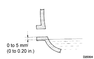
Check that the oil surface is within 5 mm (0.20 in.) below the lowest point of the transmission filler plug opening.
Oil grade GL-4 Viscosity SAE 75W-90 Capacity 2.6 liters (2.7 US qts, 2.3 lmp.qts) Note
-
Problems may occur when the oil level is too high or too low.
-
After replacing the oil, drive the vehicle and check the oil level again.
-
-
Check for oil leakage if the oil level is low.
-
Install the transmission filler plug and a new gasket.
- Torque:
- 37 N*m { 377 kgf*cm, 27 ft.*lbf }
-
-
ADD AUTOMATIC TRANSMISSION FLUID (for Automatic Transmission)
-
BLEED AIR FROM POWER STEERING SYSTEM
-
Check the fluid level.
-
Jack up the front of the vehicle and support it with stands.
-
Turn the steering wheel.
-
With the engine stopped, turn the steering wheel slowly from lock to lock several times.
-
-
Lower the vehicle.
-
Start the engine.
-
Run the engine at idle for a few minutes.
-
-
Turn the steering wheel.
-
With the engine idling, turn the steering wheel left or right to the full lock position and keep it there for 2 to 3 seconds, then turn the steering wheel to the opposite full lock position and keep it there for 2 to 3 seconds.
-
Repeat several times.
-
-
Stop the engine.
-
Check for foaming or emulsification.
If the system has to be bled twice because of forming or emulsification, be sure to check for fluid leaks in the system.
-
Check the fluid level Click here.
-
-
PERFORM REGISTRATION
-
Perform pilot quantity learning Click here.
-
-
PERFORM INITIALIZATION
-
Perform initialization of the crank time compensation reset function Click here.
-
-
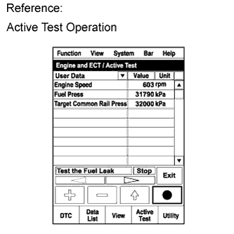
INSPECT FOR FUEL LEAK
-
Perform the Active Test.
-
Connect the intelligent tester to the DLC3.
-
Turn the ignition switch to ON.
-
Turn the intelligent tester on.
-
Enter the following menus: Powertrain / ECD / Active Test.
-
Perform the Active Test.
Intelligent Tester Display Test Part Control Range Diagnostic Notes Test the Fuel Leak Pressurize common rail interior and check for fuel leaks Stop/Start
-
Fuel pressure inside common rail increased to specified value and engine speed increased to 2000 rpm when Active Test is performed
-
Above conditions preserved while Active Test is being performed
-
-
-
-
INSPECT FOR OIL LEAK
-
Start the engine. Make sure that there are no oil leaks from the areas that were worked on.
-
-
INSPECT FOR COOLANT LEAK
CAUTION:
Do not remove the radiator cap while the engine and radiator are still hot. Hot, pressurized engine coolant and steam may be released and cause serious burns.
-
Fill the radiator with coolant and attach a radiator cap tester to the radiator.
-
Warm up the engine.
-
Using a radiator cap tester, increase the pressure inside the radiator to 137 kPa (1.4 kgf/cm2, 19.9 psi), and check that the pressure does not drop.
Tech Tips
If the pressure drops, check the hoses, radiator and water pump for leaks. If no external leaks are found, check the heater core, cylinder block and cylinder head.
-
-
INSPECT FOR POWER STEERING FLUID LEAK
-
INSPECT POWER STEERING FLUID LEVEL
-
Keep the vehicle level.
-
With the engine stopped, check the fluid level in the reservoir.
If necessary, add fluid.
Fluid ATF DEXRON II or III, or equivalent Tech Tips
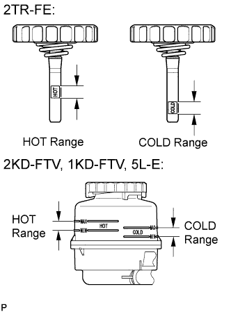
If the fluid is hot, check that the fluid level is within the HOT range on the oil reservoir or cap dipstick. If the fluid is cold, check that the fluid level is within the COLD range.
-
Start the engine and run at idle.
-
Turn the steering wheel from lock to lock several times to raise fluid temperature.
Fluid temperature 75 to 80°C (167 to 176°F) -
Check for foaming or emulsification.
If foaming or emulsification is identified, bleed the power steering system Click here.
-
With the engine idling, measure the fluid level in the oil reservoir.
-
Stop the engine.
-
Wait a few minutes and remeasure the fluid level in the oil reservoir.
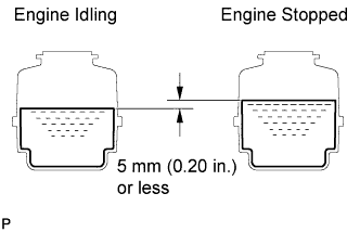
Maximum fluid level rise 5 mm (0.20 in.) If a problem is found, bleed the power steering system Click here.
-
Check the fluid level.
-
-
INSPECT ENGINE OIL LEVEL
-
w/ DPF: Click here
-
w/o DPF: Click here
-
-
INSPECT AUTOMATIC TRANSMISSION FLUID LEVEL (for Automatic Transmission)
Tech Tips
Drive the vehicle so that the engine and transmission are at normal operating temperature.
Fluid temperature 70 to 80 °C (158 to 176 °F)
-
Park the vehicle on a level surface and set the parking brake.
-
With the engine idling and the brake pedal depressed, move shift the lever into all positions from P to L and return to the P position.
-
Take out the dipstick and wipe it clean.
-
Put it back all the way.
-
Take it out again and check that the fluid level is within the HOT range.
If the fluid level is below the HOT range, add new fluid and recheck the fluid level. If the fluid level exceeds the HOT range, drain the fluid once, add the proper amount of new fluid and recheck the fluid level.
-
-
INSPECT SHIFT LEVER POSITION (for Automatic Transmission)
-
When shifting from P position only with ignition switch ON and depress the break pedal.
-
Make sure that the shifting lever moves smoothly and can be moderately operated.
-
When starting engine, make sure that the vehicle moves forward when shifting from N to D position and moves reward when shifting R position.
-
-
ADJUST SHIFT LEVER POSITION (for Automatic Transmission)
-
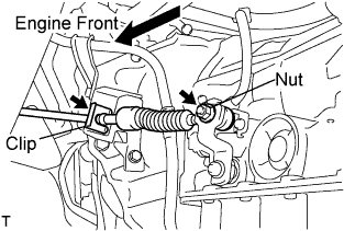
Remove a clip, nut, and disconnect between the control shaft lever to transmission control cable assembly from the control shaft lever and transmission control cable bracket No.1.
-
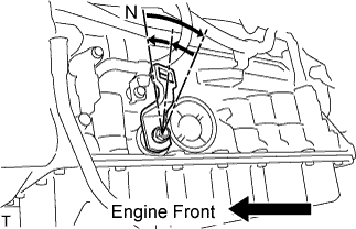
Turn the control shaft lever until stop to a clockwise direction, return the control shaft lever 2 notches to N position.
-

Set the shift lever to N position while holding the shift lever lightly toward the R position side and install it.
- Torque:
- 15 N*m { 150 kgf*cm, 11 ft.*lbf }
Note
Tighten the nut with it closing up cranky.
-
Inspect the operation condition and work.
-
-
INSPECT FOR EXHAUST GAS LEAK
-
If gas is leaking, tighten the areas necessary to stop the leak. Replace damaged parts as necessary.
-
-
INSPECT FOR REFRIGERANT LEAK
-
After recharging refrigerant gas, check for leakage of refrigerant gas using a halogen leak detector.
-
Carry out the test under the following conditions:
-
Stop the engine.
-
Secure good ventilation (the gas leak detector may react to volatile gases which are not refrigerant, such as evaporated gasoline and exhaust gas).
-
Repeat the test 2 or 3 times.
-
Make sure that there is some refrigerant remaining in the refrigeration system.
When the compressor is off: approx. 392 to 588 kPa (4 to 6 kgf/cm2, 57 to 85 psi)
-
-
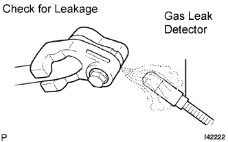
Using a gas leak detector, check for leakage of the refrigerant line.
-
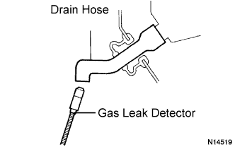
Bring the gas leak detector close to the drain hose with the detector's power off.
Tech Tips
-
After the blower motor has stopped, let the cooling unit stand for more than 15 minutes.
-
Bring the gas leak detector sensor under the drain hose.
-
When bringing the gas leak detector close to the drain hose, make sure that the gas leak detector does not react to volatile gases.
If such reaction is unavoidable, the vehicle must be lifted up.
-
-
If a gas leak is not detected on the drain hose, remove the blower motor control from the cooling unit. Insert the gas leak detector sensor into the unit and perform the test.
-
Disconnect the pressure switch connector and leave it for approximately 20 minutes. Bring the gas leak detector close to the pressure switch and perform the test.
-
-
INSTALL NO. 2 ENGINE SERVICE HOLE COVER
-
Install the No. 2 engine service hole cover with the 3 bolts.
- Torque:
- 9.0 N*m { 92 kgf*cm, 80 in.*lbf }
-
Return the carpet to its original position and attach the clips.
-
-
INSTALL ENGINE SERVICE HOLE SUB COVER SUB-ASSEMBLY
-
Install the engine service hole sub cover with the 5 bolts.
- Torque:
- 13 N*m { 133 kgf*cm, 10 ft.*lbf }
-
-
INSTALL FRONT DOOR SCUFF PLATE RH
-
INSTALL FRONT SEAT ASSEMBLY RH
-

Connect the front seat inner belt assembly connector and install the front seat assembly.
-
Align the front seat assembly adjuster pin with the holes in the body.
-
Move the front seat assembly to the rearmost position.
Note
Make sure that the front seat assembly is securely locked.
-
Temporarily tighten the 2 bolts on the front side of the front seat assembly.
-
Move the front seat assembly fully forward.
Note
Make sure that the front seat assembly is securely locked.
-
Temporarily tighten the 2 bolts on the rear side of the front seat assembly.
-
Move the front seat assembly to the rearmost position.
Note
Make sure that the front seat assembly is securely locked.
-
Fully tighten the 2 bolts on the front side of the front seat assembly in the order of outer and inner side.
- Torque:
- 39 N*m { 398 kgf*cm, 29 ft.*lbf }
-
Move the front seat assembly fully forward.
Note
Make sure that the front seat assembly is securely locked.
-
Fully tighten the 2 bolts on the rear side of the front seat assembly in the order of outer and inner side.
- Torque:
- 39 N*m { 398 kgf*cm, 29 ft.*lbf }
-
-
INSPECT ENGINE IDLE SPEED
Note
Turn all electrical systems off.
-
Warm up and stop the engine.
-
When using the intelligent tester:
-
Connect the intelligent tester to the DLC3.
-
Turn the ignition switch to ON.
-
Enter the following menus: Powertrain / Engine / Data List / Engine Speed.
Tech Tips
Refer to the intelligent tester operator's manual for further information regarding the selection of the Data List.
-
Inspect the engine idling speed.
Idling speed 700 to 800 rpm -
Fully depress the accelerator pedal.
-
Check the maximum speed.
Maximum speed 4500 to 4700 rpm -
Turn the ignition switch off.
-
Disconnect the intelligent tester from the DLC3.
-
-
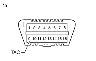
Text in Illustration *a Front view of DLC3 When not using the intelligent tester:
-
Install SST to terminal 9 (TAC) of DLC3, and then connect a tachometer.
- SST
- 09843-18040
Note
Examine the terminal numbers before connecting them. Connecting SST to the wrong terminal can damage the engine.
-
Turn the ignition switch to ON.
-
Inspect the engine idling speed.
Idling speed 700 to 800 rpm -
Fully depress the accelerator pedal.
-
Check the maximum speed.
Maximum speed 4500 to 4700 rpm -
Turn the ignition switch off.
-
Disconnect the tachometer.
-
Remove SST from terminal 9.
-
-
-
INSPECT AND ADJUST FRONT WHEEL ALIGNMENT
-
INSPECT ABS SPEED SENSOR SIGNAL