ENGINE ASSEMBLY (w/ DPF) REMOVAL

Note
-
When replacing the injectors (including shuffling the injectors between the cylinders), common rail or cylinder head, it is necessary to replace the injection pipes with new ones.
-
When replacing the fuel supply pump, common rail, cylinder block, cylinder head, cylinder head gasket or timing gear case, it is necessary to replace the fuel inlet pipe with a new one.
-
After removing the injection pipes, clean them with a brush and compressed air.
-
PLACE FRONT WHEELS FACING STRAIGHT AHEAD
-
RECOVER REFRIGERANT FROM REFRIGERATION SYSTEM
-
Start up the engine.
-
Turn the A/C switch on.
-
Operate the cooler compressor at an engine rpm of approximately 1,000 for 5 to 6 minutes to circulate the refrigerant and collect compressor oil remaining in each component into the cooler compressor as much as possible.
-
Stop the engine.
-
Using SST, let the refrigerant gas out.
- SST
- 07110-58060 ( 07117-58080, 07117-58090, 07117-78050, 07117-88060, 07117-88070, 07117-88080 )
-
-
REMOVE FRONT WHEELS
-
DISCONNECT CABLE FROM NEGATIVE BATTERY TERMINAL
-
DRAIN ENGINE COOLANT
CAUTION:
Do not remove the radiator reservoir cap sub-assembly while the engine and radiator are still hot. Pressurized, hot engine coolant and steam may be released and cause serious burns.
-
Loosen the radiator drain cock plug.

Text in Illustration *1 Bleeder Plug *2 Radiator Reservoir Cap Sub-assembly *3 Radiator Reservoir Assembly *4 Cylinder Block Drain Cock Plug *5 Radiator Drain Cock Plug - - -
Remove the radiator reservoir cap sub-assembly.
-
Loosen the cylinder block drain cock plug (on the engine oil cooler cover), and drain the engine coolant.
-
Tighten the radiator drain cock plug.
-
Tighten the cylinder block drain cock plug (on the engine oil cooler cover).
- Torque:
- 8.0 N*m { 82 kgf*cm, 71 in.*lbf }
-
-
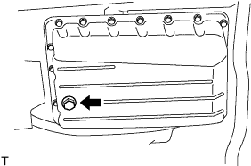
DRAIN ENGINE OIL
-
Remove the oil filler cap.
-
Remove the oil pan drain plug and gasket, and then drain the engine oil into a container.
-
Wipe the oil pan and oil pan drain plug.
-
Install a new gasket and the oil pan drain plug.
- Torque:
- 34 N*m { 347 kgf*cm, 25 ft.*lbf }
-
-
REMOVE TRANSMISSION OIL LEVEL GAUGE SUB-ASSEMBLY (for Automatic Transmission)
-
Remove the transmission oil level gauge sub-assembly from the transmission oil filler tube sub-assembly.
-
-
DRAIN MANUAL TRANSMISSION OIL (for Manual Transmission)
-
Remove the filler plug and gasket.
-
Remove the drain plug and gasket, and drain the oil.
-
Install the drain plug with a new gasket.
- Torque:
- 37 N*m { 377 kgf*cm, 27 ft.*lbf }
-
-
DRAIN AUTOMATIC TRANSMISSION FLUID (for Automatic Transmission)
-
Remove the drain plug and gasket and drain automatic transmission fluid.
-
Install the drain plug with a new gasket.
- Torque:
- 20 N*m { 204 kgf*cm, 15 ft.*lbf }
-
-
REMOVE FRONT SEAT ASSEMBLY RH
-

Move the front seat assembly fully forward.
-
Remove the 2 bolts on the rear side of the seat.
-
Move the front seat assembly to the rearmost position.
-
Remove the 2 bolts on the front side of the seat.
-
Move the front seat assembly to the center of the seat slide rail. Set the seatback in the upright position.
-
Disconnect the front seat inner belt assembly connector.
-
Remove the front seat assembly.
-
-
REMOVE FRONT DOOR SCUFF PLATE RH
-
REMOVE ENGINE SERVICE HOLE SUB COVER SUB-ASSEMBLY
-
Roll up the carpet and remove the engine service hole sub cover.
-
-
REMOVE NO. 2 ENGINE SERVICE HOLE COVER
-
Detach the clips and fold back the carpet.
-
Remove the 3 bolts and No. 2 engine service hole cover.
-
-
REMOVE GENERATOR ASSEMBLY
-
REMOVE FRONT EXHAUST PIPE ASSEMBLY
-
REMOVE TURBOCHARGER SUB-ASSEMBLY
-
REMOVE EXHAUST MANIFOLD
-
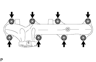
Remove the 8 nuts, 8 plate washers, 8 collars and exhaust manifold.
-
-
REMOVE NO. 1 COMPRESSOR MOUNTING BRACKET
-
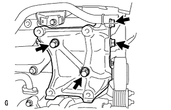
Remove the 4 bolts and No. 1 compressor mounting bracket.
-
-
REMOVE V-RIBBED BELT TENSIONER ASSEMBLY
-
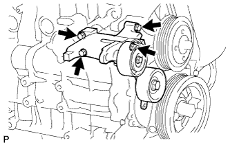
Remove the 4 bolts and V-ribbed belt tensioner.
-
-
DISCONNECT NO. 1 RADIATOR HOSE
-
Disconnect the No. 1 radiator hose from the water inlet.
-
-
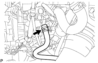
DISCONNECT HEATER HOSE
-
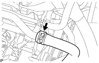
Disconnect the heater hose from the water by-pass pipe.
-
-
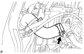
DISCONNECT NO. 3 WATER BY-PASS HOSE
-
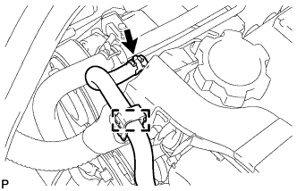
Detach the clamp and disconnect the No. 3 water by-pass hose from the No. 2 water by-pass pipe.
-
-
DISCONNECT OIL RETURN HOSE
-
Detach the 2 clamps and disconnect the oil return hose from the intake manifold.
-
-
REMOVE NO. 4 AIR HOSE
-
Loosen the 2 hose clamps.
-
Remove the No. 4 air hose.
-
-
DISCONNECT NO. 4 RADIATOR HOSE
-
Remove the No. 4 radiator hose from the water outlet.
-
-
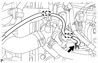
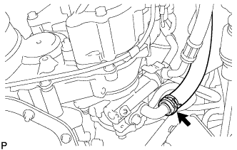
DISCONNECT NO. 2 FUEL HOSE
-
Disconnect the No. 2 fuel hose from the No. 3 nozzle leakage pipe.
-
-
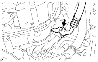
DISCONNECT NO. 1 FUEL HOSE
-
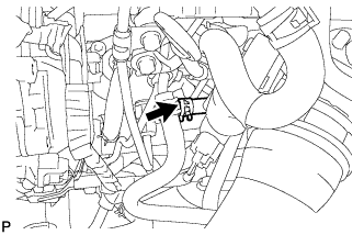
Disconnect the No. 1 fuel hose from the fuel supply pump.
-
-
DISCONNECT VACUUM HOSE
-
Disconnect the vacuum hose from the vacuum pump.
-
-
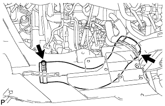
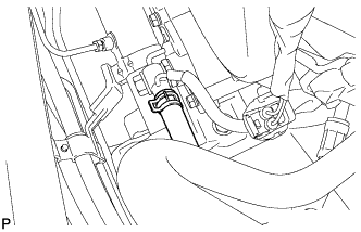
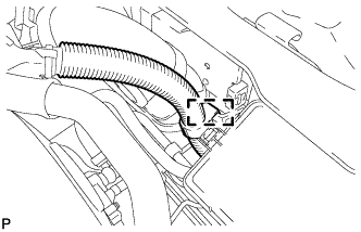
DISCONNECT ENGINE WIRE
-
Remove the bolt.
-
Detach the clamp to disconnect the engine wire.
-
Disconnect the ECM connector Click here.
-
Disconnect the 5 connectors.
-
Detach the 5 clamps.
-
-
DISCONNECT ENGINE ROOM MAIN WIRE
-
Disconnect the 5 connectors.
-
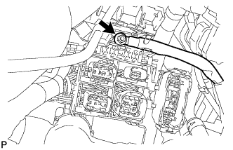
Open the cover and remove the nut.
-
Detach the clamp and disconnect the engine room main wire.
-
-
DISCONNECT VANE PUMP OIL RESERVOIR ASSEMBLY
-
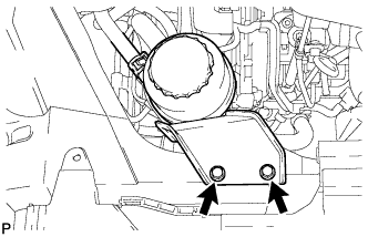
Remove the 2 bolts and disconnect the vane pump oil reservoir.
-
-
REMOVE PROPELLER SHAFT ASSEMBLY
-
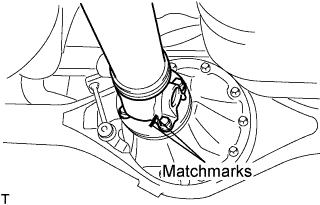
Put matchmarks on both flanges.
-
Remove the 4 nuts, bolts and washers.
Tech Tips
If the flange connection is hard to separate, temporarily tighten one nut only and evenly tap the flange with a brass bar and hammer to separate the propeller shaft assembly from the differential companion flange.
-
Remove the propeller shaft assembly.
-
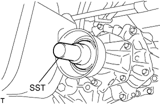
Insert SST in the transmission to prevent oil leakage.
Note
Do not damage the oil seal.
-
Use the following SST for the automatic transmission
- SST
- 09325-40010
-
Use the following SST for the manual transmission
- SST
- 09325-20010
-
-
-
REMOVE MANUAL TRANSMISSION ASSEMBLY (for Manual Transmission)
-
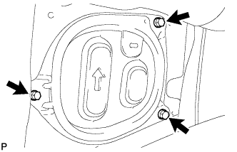
REMOVE DRIVE PLATE AND TORQUE CONVERTER CLUTCH SETTING BOLT (for Automatic Transmission)
-
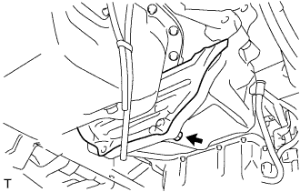
Remove the bolt and drive plate cover from the automatic transmission assembly.
-
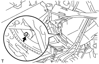
Turn the crankshaft pulley and remove the 6 drive plate and torque converter clutch setting bolts.
-
-
REMOVE AUTOMATIC TRANSMISSION ASSEMBLY (for Automatic Transmission)
-
REMOVE CLUTCH COVER ASSEMBLY (for Manual Transmission)
-
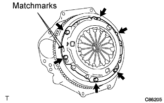
Put matchmarks on the clutch cover assembly and the flywheel sub-assembly.
-
Loosen each set bolt one turn at a time until spring tension is released.
-
Remove the set bolts, and pull off the clutch cover assembly.
Note
Do not drop the clutch disc assembly.
-
-
REMOVE CLUTCH DISC ASSEMBLY (for Manual Transmission)
Note
Keep the lining part of the clutch disc assembly, the pressure plate and surface of the flywheel sub-assembly away from oil and foreign matter.
-
REMOVE FLYWHEEL SUB-ASSEMBLY (for Manual Transmission)
-
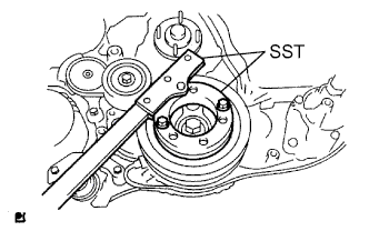
Using SST, hold the crankshaft pulley.
- SST
- 09213-58014
- 09330-00021
-
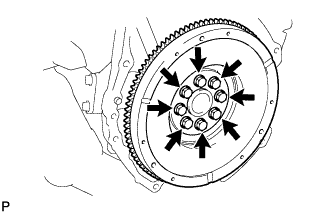
Remove the 8 bolts and flywheel.
-
-
REMOVE PUMP IMPELLER DRIVE PLATE (for Automatic Transmission)
-
Using SST, hold the crankshaft pulley.
- SST
- 09213-58014
- 09330-00021
-
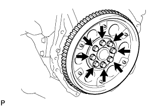
Remove the 8 bolts, rear drive plate spacer, pump impeller drive plate and flywheel.
-
-
REMOVE REAR END PLATE
-
Remove the bolt and rear end plate.
-
-
DISCONNECT FRONT SPEED SENSOR LH
-
Remove the 2 bolts, and separate the speed sensor from the steering knuckle.
Note
-
Be careful not to damage the speed sensor.
-
Prevent foreign matter from adhering to the speed sensor.
-
-
-
DISCONNECT FRONT SPEED SENSOR RH
Tech Tips
Use the same procedure described for the LH side.
-
DISCONNECT FRONT DISC BRAKE CALIPER ASSEMBLY LH
-
Remove the 2 bolts, and disconnect the brake caliper assembly.
Note
Use a wire or an equivalent to keep the brake caliper from hanging down by the flexible hose.
-
-
DISCONNECT FRONT DISC BRAKE CALIPER ASSEMBLY RH
Tech Tips
Use the same procedure described for the LH side.
-
DISCONNECT FRONT SUSPENSION ARM SUB-ASSEMBLY UPPER LH
-
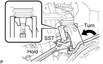
Remove the cotter pin and loosen the nut.
- SST
- 09628-62011
Note
Do not remove the nut.
-
Using SST, separate the steering knuckle from the suspension upper arm and remove the nut.
Note
-
Fix the steering knuckle with a wire so that the flexible hose does not receive excessive force.
-
Do not damage the ball joint dust cover.
-
-
-
DISCONNECT FRONT SUSPENSION ARM SUB-ASSEMBLY UPPER RH
Tech Tips
Use the same procedure described for the LH side.
-
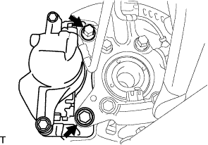
DISCONNECT FRONT SHOCK ABSORBER ASSEMBLY LH
-
Remove the bolt and separate the front shock absorber from the front suspension lower arm.
-
-
DISCONNECT FRONT SHOCK ABSORBER ASSEMBLY RH
Tech Tips
Use the same procedure described for the LH side.
-
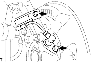
DISCONNECT STEERING TORQUE SHAFT ASSEMBLY
-
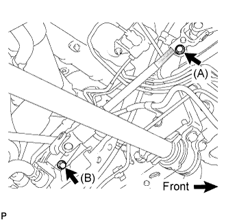
Loosen bolt (A) and remove bolt (B), then slide the steering torque shaft assembly.
Tech Tips
-
Do not remove bolt (A).
-
Do not disconnect the steering torque shaft assembly from the power steering link assembly.
-
-
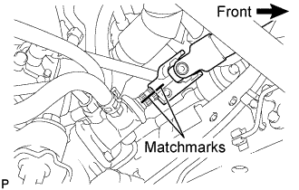
Put matchmarks on the steering torque shaft assembly and the power steering link assembly.
-
Separate the steering torque shaft assembly from the power steering link assembly.
-
-
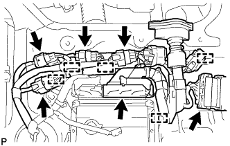
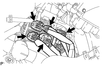
REMOVE ENGINE ASSEMBLY
-
Set an engine lifter in place.
-
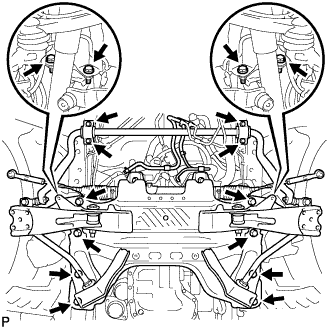
Remove the 16 bolts shown in the illustration.
-
Operate the engine lifter and slowly remove the engine from the vehicle.
-
-
INSTALL ENGINE HANGERS
-
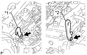
Text in Illustration *1 Upper No. 1 Engine Hanger *2 No. 2 Engine Hanger Install a No. 1 engine hanger and No. 2 engine hanger with 2 bolts as shown in the illustration.
- Torque:
- for upper No. 1 engine hanger
- 25 N*m { 255 kgf*cm }
- for No. 2 engine hanger
- 60 N*m { 612 kgf*cm }
Note
Install the engine hangers with new bolts.
Tech Tips
Upper No. 1 Engine Hanger 12284-30020 No. 2 Engine Hanger 12282-67030 Bolt 91552-81025 and 91642-81030 -
Attach an engine sling device and hang the engine with a chain block.
-
-
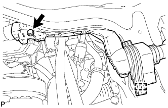
DISCONNECT NO. 1 OIL RESERVOIR TO PUMP HOSE
-
Remove the clip and separate the No.1 oil reservoir to pump hose.
-
-
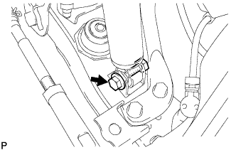
DISCONNECT PRESSURE FEED TUBE ASSEMBLY
-
Remove the union bolt and separate the pressure feed tube assembly.
-
-
REMOVE FRONT SUSPENSION CROSSMEMBER SUB-ASSEMBLY
-
Remove the 4 bolts and front suspension crossmember.
-
-
REMOVE FRONT ENGINE MOUNTING INSULATOR
-
Remove the 2 nuts, 2 engine mounting stabilizers and 2 front engine mounting insulators.
-
-
INSTALL ENGINE STAND
-
Install the engine to an engine stand with the bolts.
-
Remove the engine sling device and chain block.
-
Remove the 2 bolts and 2 engine hangers.
-
-
REMOVE ENGINE WIRE
-
Remove the engine wire from the engine.
-
-
REMOVE VANE PUMP ASSEMBLY
-
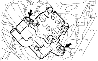
Remove the 2 nuts and the vane pump assembly.
-
Remove the vane pump O-ring from the vane pump assembly.
-
-
REMOVE VACUUM PUMP ASSEMBLY
-
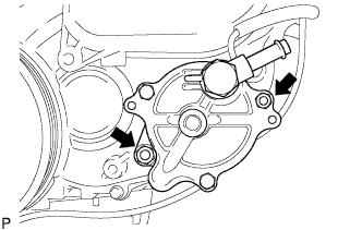
Remove the 2 nuts, vacuum pump and 2 O-rings.
-
-
REMOVE TIMING BELT
-
REMOVE NO. 1 TIMING BELT IDLER SUB-ASSEMBLY
-
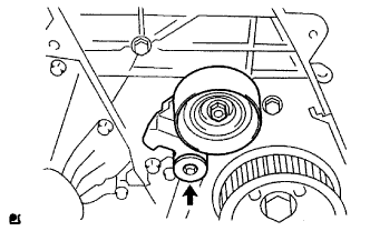
Using a 10 mm hexagon wrench, remove the bolt, No. 1 timing belt idler and washer.
-
-
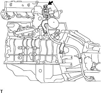
REMOVE ENGINE COOLANT TEMPERATURE SENSOR
-
Disconnect the engine coolant temperature sensor connector.
-
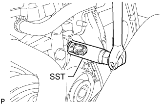
Using SST, remove the engine coolant temperature sensor and gasket.
- SST
- 09817-33190
-
-
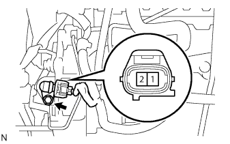
REMOVE CRANKSHAFT POSITION SENSOR
-
TYPE A:
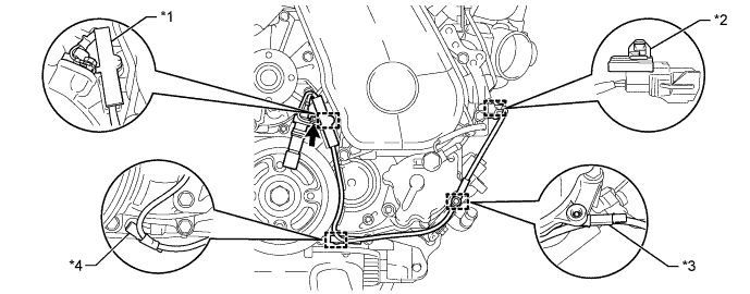
Text in Illustration *1 Clamp *2 Wire Harness Clamps (A) *3 Wire Harness Clamps (B) *4 Wire Harness Clamps (C)
-
Detach the 2 wire harness clamps (B, C).
-
Disconnect the crankshaft position sensor connector.
-
Detach the crankshaft position sensor connector from the No. 1 vacuum transmitting pipe.
-
Remove the clamp.
Note
-
Make sure that no portion of the clamp remains in the clamp installation hole. If there is any portion of the clamp remaining, remove it.
-
Do not reuse the clamp.
-
-
Remove the bolt and crankshaft position sensor.
-
Remove the wire harness clamp (A) from the crankshaft position sensor.
-
-
TYPE B:
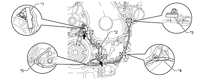
Text in Illustration *1 Clamp *2 Bracket (Clamp) *3 Wire Harness Clamps (A) *4 Wire Harness Clamps (B) *5 Wire Harness Clamps (C) - -
-
Detach the 2 wire harness clamps (B, C).
-
Disconnect the crankshaft position sensor connector.
-
Detach the crankshaft position sensor connector from the No. 1 vacuum transmitting pipe.
-
Remove the clamp.
Note
-
Make sure that no portion of the clamp remains in the clamp installation hole. If there is any portion of the clamp remaining, remove it.
-
Do not reuse the clamp.
-
-
Remove the bolt and bracket (clamp).
-
Remove the bolt and crankshaft position sensor.
-
Remove the wire harness clamp (A) from the crankshaft position sensor.
-
Detach the 2 wire harness clamps from the bracket (clamp).
-
-
-
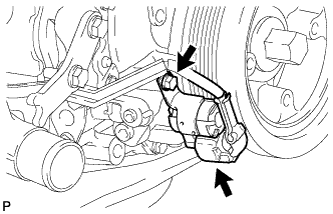
REMOVE CAMSHAFT POSITION SENSOR
-
Disconnect the camshaft position sensor connector.
-
Remove the bolt and the camshaft position sensor.
-
-
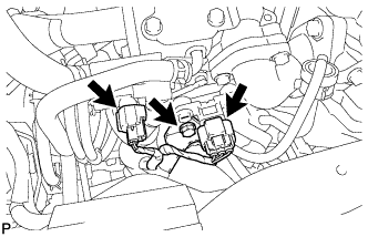
REMOVE OIL PRESSURE SWITCHING VALVE ASSEMBLY
-
Disconnect the oil pressure switching valve connector.
-
Remove the bolt and oil pressure switching valve.
-
-
REMOVE DIESEL THROTTLE BODY ASSEMBLY
-
w/o DPF:
-
Disconnect the diesel turbo pressure sensor connector and vacuum switching valve connector.
-
Remove the bolt and disconnect the wire harness clamp.
-
-
Disconnect the 2 diesel throttle body connectors.
-
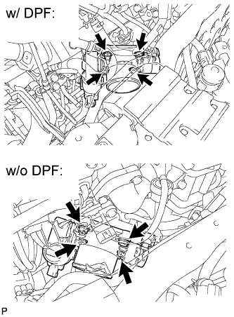
Remove the 2 bolts, 2 nuts, diesel throttle body and gasket.
-
-
REMOVE COMMON RAIL ASSEMBLY
-
REMOVE ELECTRIC EGR CONTROL VALVE ASSEMBLY
-
REMOVE EGR COOLER ASSEMBLY
-
REMOVE GLOW PLUG ASSEMBLY
-
REMOVE FUEL SUPPLY PUMP ASSEMBLY
-
REMOVE CRANKSHAFT PULLEY
-
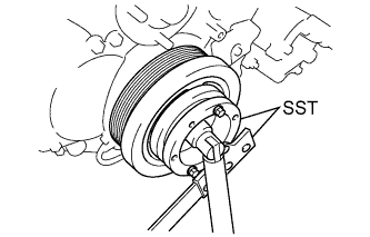
Using SST, hold the crankshaft pulley and loosen the pulley bolt.
- SST
- 09213-58014
- 09330-00021
-
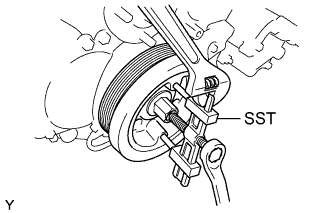
Using SST, remove the pulley bolt and crankshaft pulley.
- SST
- 09950-50013 ( 09951-05010, 09952-05010, 09953-05020, 09954-05021 )
-
-
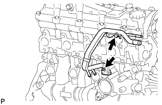
REMOVE NO. 5 WATER BY-PASS PIPE SUB-ASSEMBLY
-
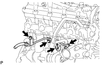
Disconnect the water hose from the No. 2 water by-pass hose.
-
Remove the 2 bolts, nut and No. 5 water by-pass pipe.
-
-
REMOVE NO. 2 WATER BY-PASS PIPE
-
Remove the bolt, nut, No. 2 water by-pass pipe and gasket.
-
-
REMOVE WATER INLET
-
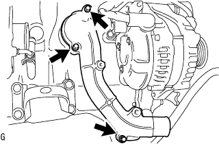
Remove the 3 bolts and water inlet.
-
-
REMOVE THERMOSTAT
-
Remove thermostat and gasket.
-
-
REMOVE NO. 2 CYLINDER BLOCK INSULATOR
-
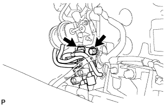
REMOVE INTAKE MANIFOLD STAY
-
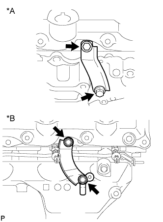
Text in Illustration *A w/ DPF *B w/o DPF Remove the 2 bolts and manifold stay.
-
-
REMOVE NO. 1 INTAKE MANIFOLD INSULATOR
-
Remove the No. 1 intake manifold insulator from the intake manifold.
-
-
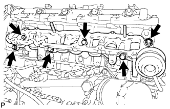
REMOVE INTAKE MANIFOLD
-
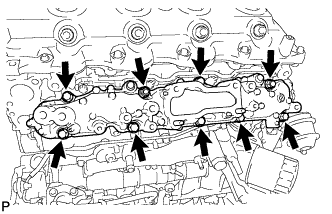
Remove the 7 bolts, 2 nuts and intake manifold.
-
Remove the gasket.
-
-
REMOVE VACUUM SWITCHING VALVE SET
-
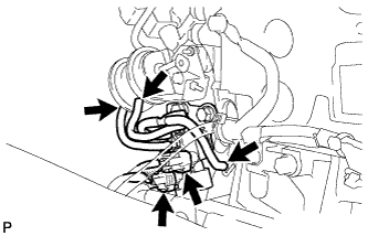
Remove the 2 connectors and 3 vacuum hoses.
-
Remove the 2 bolts and vacuum control valve set.
-
-
REMOVE SWIRL CONTROL VALVE ASSEMBLY
-
Remove the 4 bolts, 2 nuts and swirl control valve.
-
Remove the gasket.
-
-
REMOVE NO. 3 FUEL PIPE
-
REMOVE NO. 1 VACUUM TRANSMITTING PIPE SUB-ASSEMBLY
-
Disconnect the vacuum hose.
-
Remove the bolt, nut and No. 1 vacuum transmitting pipe.
-
-
REMOVE NO. 2 VACUUM TRANSMITTING PIPE SUB-ASSEMBLY
-
Remove the bolt, 2 nuts and No. 2 vacuum transmitting pipe.
-
-
REMOVE OIL COOLER COVER SUB-ASSEMBLY
-
REMOVE WATER OUTLET
-
Remove the 2 bolts, water outlet and gasket.
-
-
REMOVE FRONT NO. 1 ENGINE MOUNTING BRACKET LH
-
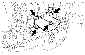
Remove the 4 bolts and front No. 1 engine mounting bracket LH.
-
-
REMOVE FRONT NO. 1 ENGINE MOUNTING BRACKET RH
-
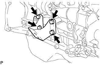
Remove the 4 bolts and front No. 1 engine mounting bracket RH.
-