ENGINE ASSEMBLY (w/ DPF) REMOVAL

Note
-
When replacing the injectors (including shuffling the injectors between the cylinders), common rail or cylinder head, it is necessary to replace the injection pipes with new ones.
-
When replacing the fuel supply pump, common rail, cylinder block, cylinder head, cylinder head gasket or timing gear case, it is necessary to replace the fuel inlet pipe with a new one.
-
After removing the injection pipes, clean them with a brush and compressed air.
-
PLACE FRONT WHEELS FACING STRAIGHT AHEAD
-
RECOVER REFRIGERANT FROM REFRIGERATION SYSTEM
-
Start up the engine.
-
Turn the A/C switch on.
-
Operate the cooler compressor at an engine rpm of approximately 1,000 for 5 to 6 minutes to circulate the refrigerant and collect compressor oil remaining in each component into the cooler compressor as much as possible.
-
Stop the engine.
-
Using SST, let the refrigerant gas out.
- SST
- 07110-58060 ( 07117-58080, 07117-58090, 07117-78050, 07117-88060, 07117-88070, 07117-88080 )
-
-
REMOVE FRONT WHEELS
-
DISCONNECT CABLE FROM NEGATIVE BATTERY TERMINAL
-
DRAIN ENGINE COOLANT
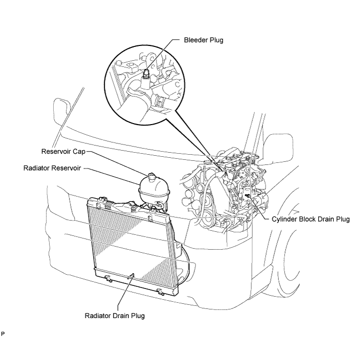
CAUTION:
To avoid the danger of being burned, do not remove the reservoir cap while the engine and radiator are still hot. Thermal expansion will cause hot engine coolant and steam to blow out from the radiator.
-
Loosen the radiator drain plug.
-
Remove the reservoir cap.
-
Loosen the cylinder block drain plug (on the engine oil cooler cover), and drain the coolant.
-
Tighten the radiator drain plug.
-
Tighten the cylinder block drain plug (on the engine oil cooler cover).
- Torque:
- 8.0 N*m { 82 kgf*cm, 71 in.*lbf }
-
-
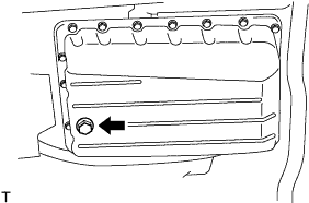
DRAIN ENGINE OIL
-
Remove the oil filler cap.
-
Remove the oil pan drain plug and gasket, and then drain the engine oil into a container.
-
Wipe the oil pan and oil pan drain plug.
-
Install a new gasket and the oil pan drain plug.
- Torque:
- 34 N*m { 347 kgf*cm, 25 ft.*lbf }
-
-
REMOVE TRANSMISSION OIL LEVEL GAUGE SUB-ASSEMBLY (for Automatic Transmission)
-
Remove the transmission oil level gauge sub-assembly from the transmission oil filler tube sub-assembly.
-
-
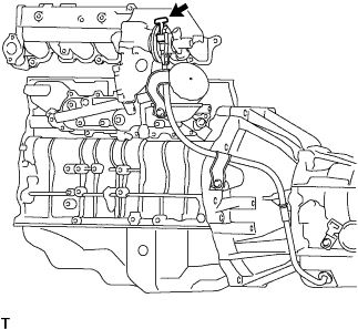
DRAIN MANUAL TRANSMISSION OIL (for Manual Transmission)
-
Remove the filler plug and gasket.
-
Remove the drain plug and gasket, and drain the oil.
-
Install the drain plug with a new gasket.
- Torque:
- 37 N*m { 377 kgf*cm, 27 ft.*lbf }
-
-
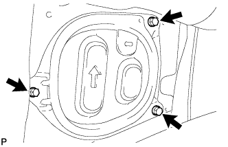
DRAIN AUTOMATIC TRANSMISSION FLUID (for Automatic Transmission)
-
Remove the drain plug and gasket and drain automatic transmission fluid.
-
Install the drain plug with a new gasket.
- Torque:
- 20 N*m { 204 kgf*cm, 15 ft.*lbf }
-
-
REMOVE FRONT SEAT ASSEMBLY RH
-

Move the front seat assembly fully forward.
-
Remove the 2 bolts on the rear side of the seat.
-
Move the front seat assembly to the rearmost position.
-
Remove the 2 bolts on the front side of the seat.
-
Move the front seat assembly to the center of the seat slide rail. Set the seatback in the upright position.
-
Disconnect the front seat inner belt assembly connector.
-
Remove the front seat assembly.
-
-
REMOVE FRONT DOOR SCUFF PLATE RH
-
REMOVE ENGINE SERVICE HOLE SUB COVER SUB-ASSEMBLY
-
Roll up the carpet and remove the engine service hole sub cover.
-
-
REMOVE NO. 2 ENGINE SERVICE HOLE COVER
-
Detach the clips and fold back the carpet.
-
Remove the 3 bolts and No. 2 engine service hole cover.
-
-
REMOVE GENERATOR ASSEMBLY
-
REMOVE FRONT EXHAUST PIPE ASSEMBLY
-
REMOVE TURBOCHARGER SUB-ASSEMBLY
-
REMOVE EXHAUST MANIFOLD
-
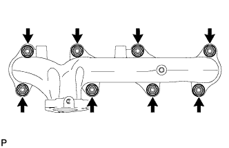
Remove the 8 nuts, 8 plate washers, 8 collars and exhaust manifold.
-
-
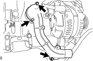
REMOVE NO. 1 COMPRESSOR MOUNTING BRACKET
-
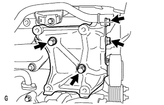
Remove the 4 bolts and No. 1 compressor mounting bracket.
-
-
REMOVE V-RIBBED BELT TENSIONER ASSEMBLY
-
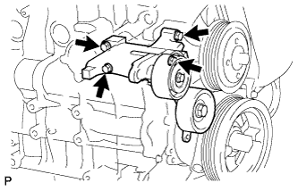
Remove the 4 bolts and V-ribbed belt tensioner.
-
-
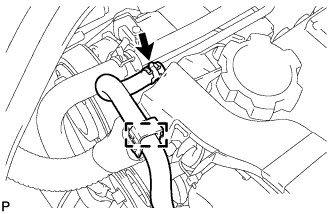
DISCONNECT NO. 1 RADIATOR HOSE
-
Disconnect the No. 1 radiator hose from the water inlet.
-
-
DISCONNECT HEATER HOSE
-
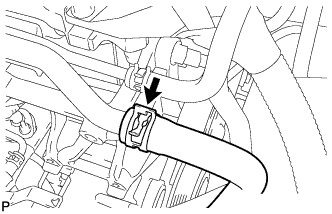
Disconnect the heater hose from the water by-pass pipe.
-
-
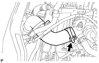
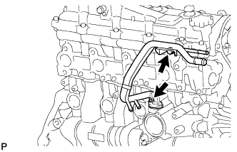
DISCONNECT NO. 3 WATER BY-PASS HOSE
-
Detach the clamp and disconnect the No. 3 water by-pass hose from the No. 2 water by-pass pipe.
-
-
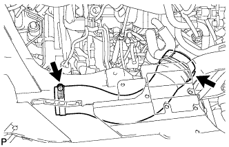
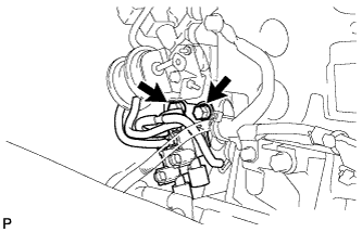
DISCONNECT OIL RETURN HOSE
-
Detach the 2 clamps and disconnect the oil return hose from the intake manifold.
-
-
REMOVE NO. 4 AIR HOSE
-
Loosen the 2 hose clamps.
-
Remove the No. 4 air hose.
-
-
DISCONNECT NO. 4 RADIATOR HOSE
-
Remove the No. 4 radiator hose from the water outlet.
-
-
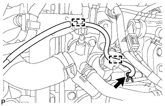
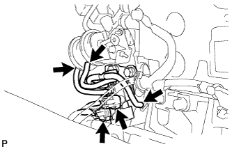
DISCONNECT NO. 2 FUEL HOSE
-
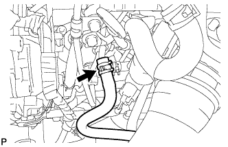
Disconnect the No. 2 fuel hose from the No. 3 nozzle leakage pipe.
-
-
DISCONNECT NO. 1 FUEL HOSE
-
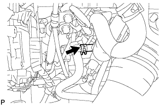
Disconnect the No. 1 fuel hose from the fuel supply pump.
-
-
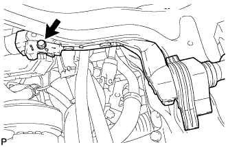
DISCONNECT VACUUM HOSE
-
Disconnect the vacuum hose from the vacuum pump.
-
-
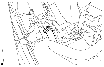
DISCONNECT ENGINE WIRE
-
Detach the 3 clips and wire harness support.
-
Disconnect the 4 ECM connectors.
-
Remove the bolt.
-
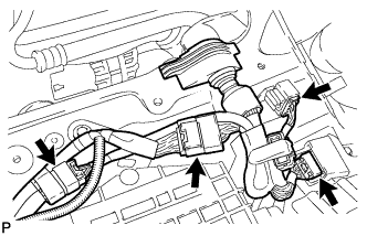
Disconnect the 4 connectors and engine wire.
-
-
DISCONNECT ENGINE ROOM MAIN WIRE
-
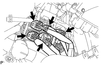
Disconnect the 5 connectors.
-
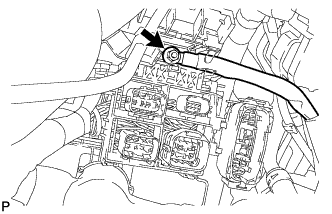
Open the cover and remove the nut.
-
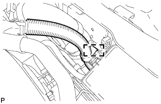
Detach the clamp and disconnect the engine room main wire.
-
-
DISCONNECT VANE PUMP OIL RESERVOIR ASSEMBLY
-
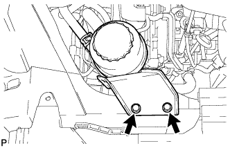
Remove the 2 bolts and disconnect the vane pump oil reservoir.
-
-
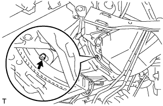
REMOVE PROPELLER SHAFT ASSEMBLY
-
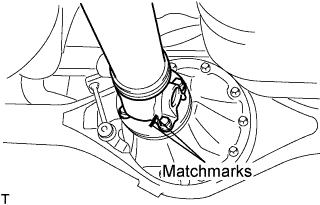
Put matchmarks on both flanges.
-
Remove the 4 nuts, bolts and washers.
Tech Tips
If the flange connection is hard to separate, temporarily tighten one nut only and evenly tap the flange with a brass bar and hammer to separate the propeller shaft assembly from the differential companion flange.
-
Remove the propeller shaft assembly.
-
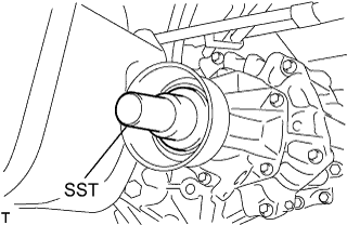
Insert SST in the transmission to prevent oil leakage.
Note
Do not damage the oil seal.
-
Use the following SST for the automatic transmission
- SST
- 09325-40010
-
Use the following SST for the manual transmission
- SST
- 09325-20010
-
-
-
REMOVE MANUAL TRANSMISSION ASSEMBLY (for Manual Transmission)
-
REMOVE DRIVE PLATE AND TORQUE CONVERTER CLUTCH SETTING BOLT (for Automatic Transmission)
-
Remove the bolt and drive plate cover from the automatic transmission assembly.
-
Turn the crankshaft pulley and remove the 6 drive plate and torque converter clutch setting bolts.
-
-
REMOVE AUTOMATIC TRANSMISSION ASSEMBLY (for Automatic Transmission)
-
REMOVE CLUTCH COVER ASSEMBLY (for Manual Transmission)
-
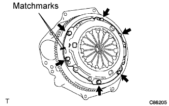
Put matchmarks on the clutch cover assembly and the flywheel sub-assembly.
-
Loosen each set bolt one turn at a time until spring tension is released.
-
Remove the set bolts, and pull off the clutch cover assembly.
Note
Do not drop the clutch disc assembly.
-
-
REMOVE CLUTCH DISC ASSEMBLY (for Manual Transmission)
Note
Keep the lining part of the clutch disc assembly, the pressure plate and surface of the flywheel sub-assembly away from oil and foreign matter.
-
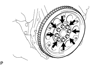
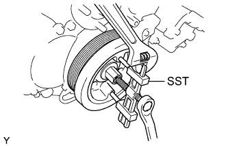
REMOVE FLYWHEEL SUB-ASSEMBLY (for Manual Transmission)
-
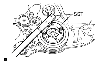
Using SST, hold the crankshaft pulley.
- SST
- 09213-58014
- 09330-00021
-
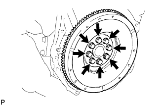
Remove the 8 bolts and flywheel.
-
-
REMOVE PUMP IMPELLER DRIVE PLATE (for Automatic Transmission)
-
Using SST, hold the crankshaft pulley.
- SST
- 09213-58014
- 09330-00021
-
Remove the 8 bolts, rear drive plate spacer, pump impeller drive plate and flywheel.
-
-
REMOVE REAR END PLATE
-
Remove the bolt and rear end plate.
-
-
DISCONNECT FRONT SPEED SENSOR LH
-
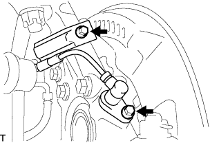
Remove the 2 bolts, and separate the speed sensor from the steering knuckle.
Note
-
Be careful not to damage the speed sensor.
-
Prevent foreign matter from adhering to the speed sensor.
-
-
-
DISCONNECT FRONT SPEED SENSOR RH
Tech Tips
Use the same procedure described for the LH side.
-
DISCONNECT FRONT DISC BRAKE CALIPER ASSEMBLY LH
-
Remove the 2 bolts, and disconnect the brake caliper assembly.
Note
Use a wire or an equivalent to keep the brake caliper from hanging down by the flexible hose.
-
-
DISCONNECT FRONT DISC BRAKE CALIPER ASSEMBLY RH
Tech Tips
Use the same procedure described for the LH side.
-
DISCONNECT FRONT SUSPENSION ARM SUB-ASSEMBLY UPPER LH
-
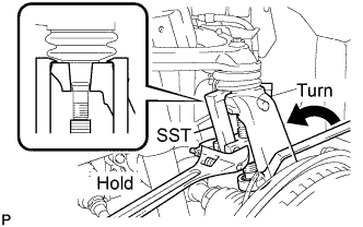
Remove the cotter pin and loosen the nut.
- SST
- 09628-62011
Note
Do not remove the nut.
-
Using SST, separate the steering knuckle from the suspension upper arm and remove the nut.
Note
-
Fix the steering knuckle with a wire so that the flexible hose does not receive excessive force.
-
Do not damage the ball joint dust cover.
-
-
-
DISCONNECT FRONT SUSPENSION ARM SUB-ASSEMBLY UPPER RH
Tech Tips
Use the same procedure described for the LH side.
-
DISCONNECT FRONT SHOCK ABSORBER ASSEMBLY LH
-
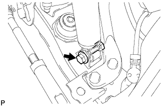
Remove the bolt and separate the front shock absorber from the front suspension lower arm.
-
-
DISCONNECT FRONT SHOCK ABSORBER ASSEMBLY RH
Tech Tips
Use the same procedure described for the LH side.
-
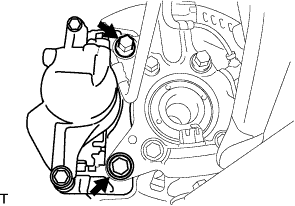
DISCONNECT STEERING TORQUE SHAFT ASSEMBLY
-
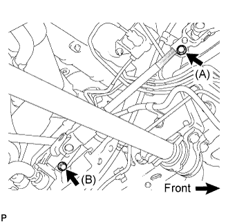
Loosen bolt (A) and remove bolt (B), then slide the steering torque shaft assembly.
Tech Tips
-
Do not remove bolt (A).
-
Do not disconnect the steering torque shaft assembly from the power steering link assembly.
-
-
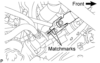
Put matchmarks on the steering torque shaft assembly and the power steering link assembly.
-
Separate the steering torque shaft assembly from the power steering link assembly.
-
-
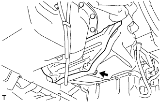
REMOVE ENGINE ASSEMBLY
-
Set an engine lifter in place.
-
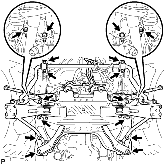
Remove the 16 bolts shown in the illustration.
-
Operate the engine lifter and slowly remove the engine from the vehicle.
-
-
INSTALL ENGINE HANGERS
-
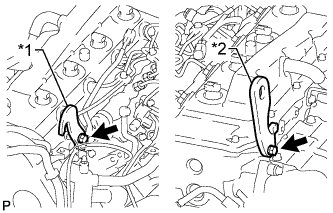
Text in Illustration *1 Upper No. 1 Engine Hanger *2 No. 2 Engine Hanger Install a No. 1 engine hanger and No. 2 engine hanger with 2 bolts as shown in the illustration.
- Torque:
- for upper No. 1 engine hanger
- 25 N*m { 255 kgf*cm }
- for No. 2 engine hanger
- 60 N*m { 612 kgf*cm }
Note
Install the engine hangers with new bolts.
Tech Tips
Upper No. 1 Engine Hanger 12284-30020 No. 2 Engine Hanger 12282-67030 Bolt 91552-81025 and 91642-81030 -
Attach an engine sling device and hang the engine with a chain block.
-
-
DISCONNECT NO. 1 OIL RESERVOIR TO PUMP HOSE
-
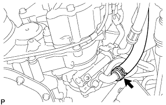
Remove the clip and separate the No.1 oil reservoir to pump hose.
-
-
DISCONNECT PRESSURE FEED TUBE ASSEMBLY
-
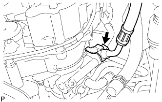
Remove the union bolt and separate the pressure feed tube assembly.
-
-
REMOVE FRONT SUSPENSION CROSSMEMBER SUB-ASSEMBLY
-
Remove the 4 bolts and front suspension crossmember.
-
-
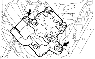
REMOVE FRONT ENGINE MOUNTING INSULATOR
-
Remove the 2 nuts, 2 engine mounting stabilizers and 2 front engine mounting insulators.
-
-
INSTALL ENGINE STAND
-
Install the engine to an engine stand with the bolts.
-
Remove the engine sling device and chain block.
-
Remove the 2 bolts and 2 engine hangers.
-
-
REMOVE ENGINE WIRE
-
Remove the engine wire from the engine.
-
-
REMOVE VANE PUMP ASSEMBLY
-
Remove the 2 nuts and the vane pump assembly.
-
Remove the vane pump O-ring from the vane pump assembly.
-
-
REMOVE VACUUM PUMP ASSEMBLY
-
Remove the 2 nuts, vacuum pump and 2 O-rings.
-
-
REMOVE TIMING BELT
-
REMOVE NO. 1 TIMING BELT IDLER SUB-ASSEMBLY
-
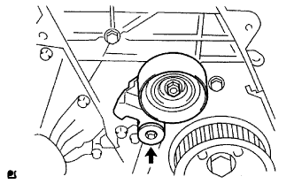
Using a 10 mm hexagon wrench, remove the bolt, No. 1 timing belt idler and washer.
-
-
REMOVE ENGINE COOLANT TEMPERATURE SENSOR
-
Disconnect the engine coolant temperature sensor connector.
-
Using SST, remove the engine coolant temperature sensor and gasket.
- SST
- 09817-33190
-
-
REMOVE CRANKSHAFT POSITION SENSOR
-
TYPE A:
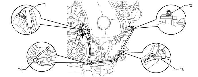
Text in Illustration *1 Clamp *2 Wire Harness Clamps (A) *3 Wire Harness Clamps (B) *4 Wire Harness Clamps (C)
-
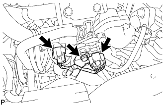
Detach the 2 wire harness clamps (B, C).
-
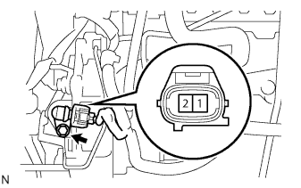
Disconnect the crankshaft position sensor connector.
-
Detach the crankshaft position sensor connector from the No. 1 vacuum transmitting pipe.
-
Remove the clamp.
Note
-
Make sure that no portion of the clamp remains in the clamp installation hole. If there is any portion of the clamp remaining, remove it.
-
Do not reuse the clamp.
-
-
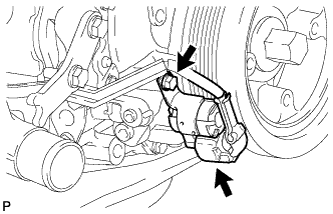
Remove the bolt and crankshaft position sensor.
-
Remove the wire harness clamp (A) from the crankshaft position sensor.
-
-
TYPE B:
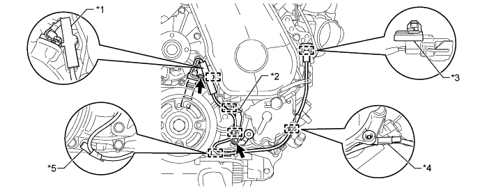
Text in Illustration *1 Clamp *2 Bracket (Clamp) *3 Wire Harness Clamps (A) *4 Wire Harness Clamps (B) *5 Wire Harness Clamps (C) - -
-
Detach the 2 wire harness clamps (B, C).
-
Disconnect the crankshaft position sensor connector.
-
Detach the crankshaft position sensor connector from the No. 1 vacuum transmitting pipe.
-
Remove the clamp.
Note
-
Make sure that no portion of the clamp remains in the clamp installation hole. If there is any portion of the clamp remaining, remove it.
-
Do not reuse the clamp.
-
-
Remove the bolt and bracket (clamp).
-
Remove the bolt and crankshaft position sensor.
-
Remove the wire harness clamp (A) from the crankshaft position sensor.
-
Detach the 2 wire harness clamps from the bracket (clamp).
-
-
-
REMOVE CAMSHAFT POSITION SENSOR
-
Disconnect the camshaft position sensor connector.
-
Remove the bolt and the camshaft position sensor.
-
-
REMOVE OIL PRESSURE SWITCHING VALVE ASSEMBLY
-
Disconnect the oil pressure switching valve connector.
-
Remove the bolt and oil pressure switching valve.
-
-
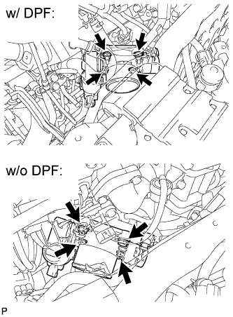
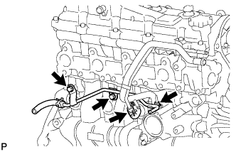
REMOVE DIESEL THROTTLE BODY ASSEMBLY
-
w/o DPF:
-
Disconnect the diesel turbo pressure sensor connector and vacuum switching valve connector.
-
Remove the bolt and disconnect the wire harness clamp.
-
-
Disconnect the 2 diesel throttle body connectors.
-
Remove the 2 bolts, 2 nuts, diesel throttle body and gasket.
-
-
REMOVE COMMON RAIL ASSEMBLY
-
REMOVE ELECTRIC EGR CONTROL VALVE ASSEMBLY
-
REMOVE EGR COOLER ASSEMBLY
-
REMOVE GLOW PLUG ASSEMBLY
-
REMOVE FUEL SUPPLY PUMP ASSEMBLY
-
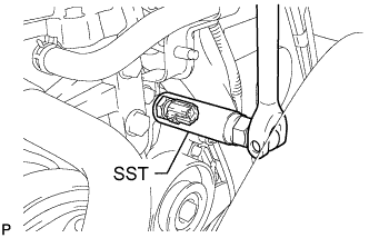
REMOVE CRANKSHAFT PULLEY
-
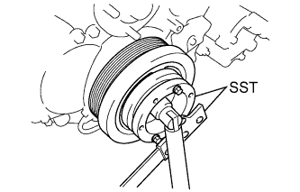
Using SST, hold the crankshaft pulley and loosen the pulley bolt.
- SST
- 09213-58014
- 09330-00021
-
Using SST, remove the pulley bolt and crankshaft pulley.
- SST
- 09950-50013 ( 09951-05010, 09952-05010, 09953-05020, 09954-05021 )
-
-
REMOVE NO. 5 WATER BY-PASS PIPE SUB-ASSEMBLY
-
Disconnect the water hose from the No. 2 water by-pass hose.
-
Remove the 2 bolts, nut and No. 5 water by-pass pipe.
-
-
REMOVE NO. 2 WATER BY-PASS PIPE
-
Remove the bolt, nut, No. 2 water by-pass pipe and gasket.
-
-
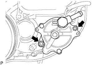
REMOVE WATER INLET
-
Remove the 3 bolts and water inlet.
-
-
REMOVE THERMOSTAT
-
Remove thermostat and gasket.
-
-
REMOVE NO. 2 CYLINDER BLOCK INSULATOR
-
REMOVE INTAKE MANIFOLD STAY
-
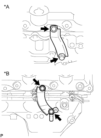
Text in Illustration *A w/ DPF *B w/o DPF Remove the 2 bolts and manifold stay.
-
-
REMOVE NO. 1 INTAKE MANIFOLD INSULATOR
-
Remove the No. 1 intake manifold insulator from the intake manifold.
-
-
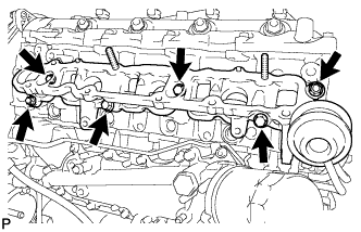
REMOVE INTAKE MANIFOLD
-
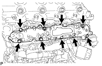
Remove the 7 bolts, 2 nuts and intake manifold.
-
Remove the gasket.
-
-
REMOVE VACUUM SWITCHING VALVE SET
-
Remove the 2 connectors and 3 vacuum hoses.
-
Remove the 2 bolts and vacuum control valve set.
-
-
REMOVE SWIRL CONTROL VALVE ASSEMBLY
-
Remove the 4 bolts, 2 nuts and swirl control valve.
-
Remove the gasket.
-
-
REMOVE NO. 3 FUEL PIPE
-
REMOVE NO. 1 VACUUM TRANSMITTING PIPE SUB-ASSEMBLY
-
Disconnect the vacuum hose.
-
Remove the bolt, nut and No. 1 vacuum transmitting pipe.
-
-
REMOVE NO. 2 VACUUM TRANSMITTING PIPE SUB-ASSEMBLY
-
Remove the bolt, 2 nuts and No. 2 vacuum transmitting pipe.
-
-
REMOVE OIL COOLER COVER SUB-ASSEMBLY
-
REMOVE WATER OUTLET
-
Remove the 2 bolts, water outlet and gasket.
-
-
REMOVE FRONT NO. 1 ENGINE MOUNTING BRACKET LH
-
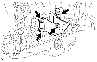
Remove the 4 bolts and front No. 1 engine mounting bracket LH.
-
-
REMOVE FRONT NO. 1 ENGINE MOUNTING BRACKET RH
-
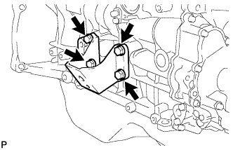
Remove the 4 bolts and front No. 1 engine mounting bracket RH.
-