KNOCK SENSOR REMOVAL

-
DISCHARGE FUEL SYSTEM PRESSURE
-
DISCONNECT CABLE FROM NEGATIVE BATTERY TERMINAL
-
REMOVE ENGINE UNDER COVER NO.1 (w/ Engine Under Cover No.1)
-
REMOVE ENGINE UNDER COVER NO.2 (w/ Engine Under Cover No.2)
-
Remove the engine under cover No.2 together with the engine side under cover LH and engine side under cover RH (for Wide Body).
-
-
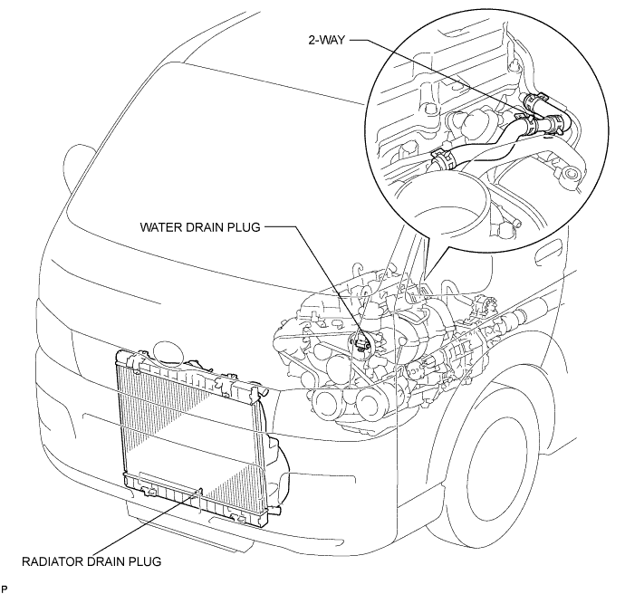
DRAIN ENGINE COOLANT
CAUTION:
Do not remove the radiator cap while the engine and radiator are still hot. Pressurized, hot engine coolant and steam may be released and cause serious burns.
-
Remove the radiator cap.
-
Loosen the radiator drain plug and a cylinder block drain plug. Then drain the coolant.
-
-
REMOVE FRONT SEAT ASSEMBLY RH (for Hi-back Seat Type)
Tech Tips
Use the same procedures described for the LH side. Click here
-
REMOVE FRONT SEAT ASSEMBLY RH (for Low-back Seat Type)
Tech Tips
Use the same procedures described for the LH side. Click here
-
REMOVE FRONT DOOR SCUFF PLATE RH
-
REMOVE ENGINE SERVICE HOLE SUB COVER SUB-ASSEMBLY
-
Roll up the carpet, and remove the 5 bolts and engine service hole sub cover.
-
-
REMOVE INTAKE AIR CONNECTOR
-
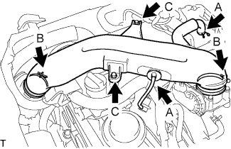
Disconnect the ventilation hose No.2 and the vacuum hose.(A)
-
Loosen the 2 hose clamp bolts.(B)
-
Remove the 2 bolts, then remove the intake air connector.(C)
-
-
REMOVE THROTTLE BODY ASSEMBLY
-
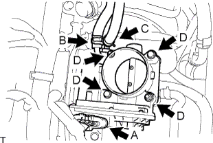
Disconnect the throttle motor connector.(A)
-
Disconnect the water by-pass hose.(B)
-
Disconnect the water by-pass hose No.2.(C)
-
Remove the 2 bolts and 2 nuts, then remove the throttle body assembly.(D)
-
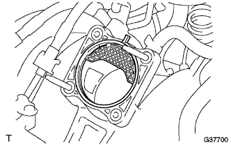
Remove the gasket from the intake manifold.
-
-
DISCONNECT FUEL HOSE
-
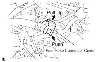
Pull the fuel hose connector cover up to release the lock. Click here
-
Disengage the fuel connector to disconnect the fuel hose. Click here
-
-
REMOVE FUEL DELIVERY PIPE SUB-ASSEMBLY
Note
Be careful not to drop the injectors when removing the delivery pipe.
-
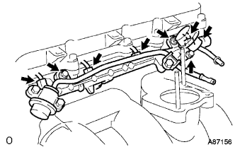
Disconnect the fuel hoses.
-
Disconnect the 4 injector connectors.
-
Remove the 2 bolts O-ring and fuel pulsation damper assembly.
-
Remove the 2 bolts and delivery pipe together with the 4 injectors.
-
Remove the delivery pipe spacers.
-
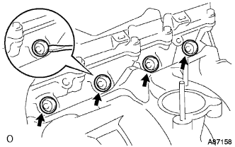
Using a screwdriver, pry out the 4 spacers from the cylinder head.
-
-
REMOVE FUEL INJECTOR ASSEMBLY
-
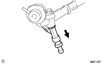
Pull out the 4 injectors from the delivery pipe.
-
Remove the O-rings from the injectors.
-
-
REMOVE TRANSMISSION OIL FILLER TUBE SUB-ASSEMBLY (for Automatic Transmission)
-
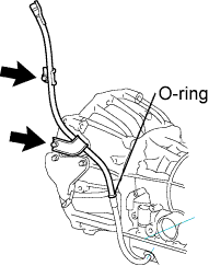
Remove the 2 bolts transmission oil filler tube sub-assembly.
-
Remove the O-ring from the oil filler tube sub-assembly.
-
-
REMOVE INTAKE MANIFOLD
-
Disconnect the vacuum hose and connector from the VSV.
-
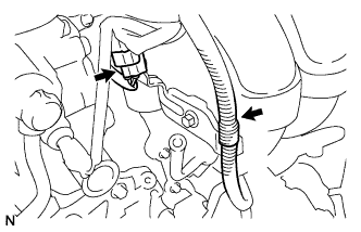
Disconnect the 2 wire harness clamps.
-
Disconnect the ventilation hose No.3 from the intake manifold.
-
Loosen the 2 clips and disconnect the brake booster hose and the fuel vapor feed hose from the intake manifold.
-
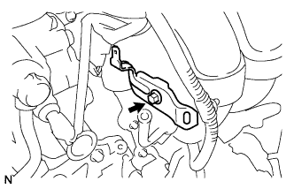
Remove the bolt and the wire harness bracket from the intake manifold.
-
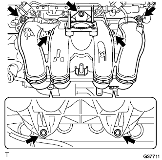
Remove the 5 bolts, 2 nuts, and intake manifold.
-
Remove the gasket from the intake manifold.
-
-
REMOVE KNOCK CONTROL SENSOR
-
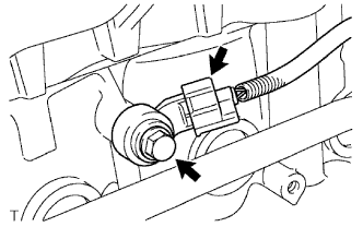
Disconnect the knock control sensor connector.
-
Remove the bolt and the knock control sensor.
-