ENGINE COOLANT TEMPERATURE SENSOR INSTALLATION

-
INSTALL E.F.I. ENGINE COOLANT TEMPERATURE SENSOR
-
Install a new gasket onto the engine coolant temperature sensor.
-
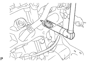
Using a 19 mm deep socket wrench, install the engine coolant temperature sensor.
- Torque:
- 20 N*m { 200 kgf*cm, 14 ft.*lbf }
-
Connect the engine coolant temperature sensor connector.
-
-
INSTALL INTAKE MANIFOLD
-
Install a new gasket onto the intake manifold.
-
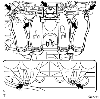
Install the 5 bolts, 2 nuts, and intake manifold.
- Torque:
- 25 N*m { 255 kgf*cm, 18 ft.*lbf }
-
Install the bolt and wire harness bracket to the intake manifold.
- Torque:
- 8.0 N*m { 82 kgf*cm, 71 in.*lbf }
-
Connect the brake booster hose and the fuel vapor feed hose with the 2 clips.
-
Connect the ventilation hose No.3 from the intake manifold.
-
Connect the 2 wire harness clamps.
-
Connect the vacuum hose and connector to the VSV.
-
-
INSTALL TRANSMISSION OIL FILLER TUBE SUB-ASSEMBLY (for Automatic Transmission)
-
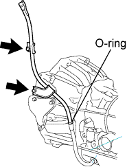
Coat a new O-ring with ATF and install the oil filler tube.
-
Install the oil filler tube with 2 bolts.
- Torque:
- 12 N*m { 125 kgf*cm, 10 ft.*lbf }
-
-
INSTALL FUEL INJECTOR ASSEMBLY
-
Apply a light coat of grease or gasoline to new O-rings and install them to the injector spacers.
Note
Make sure that the O-rings are installed between the parts correctly.
-
Install the injection spacers.
-
Apply a light coat of grease or gasoline to the place where the delivery pipe touches the O-ring.
-
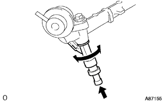
To install the fuel injector into the fuel delivery pipe, push the fuel injector while twisting it right and left.
Note
-
Be careful not to twist the O-ring.
-
After installing the fuel injector, check that it turns smoothly. If not, reinstall it with a new O-ring.
-
-
-
INSTALL FUEL DELIVERY PIPE SUB-ASSEMBLY
-
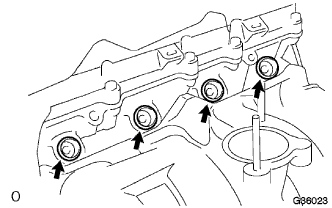
Install the 4 spacers to the cylinder head.
-
Install the delivery pipe spacers.
-
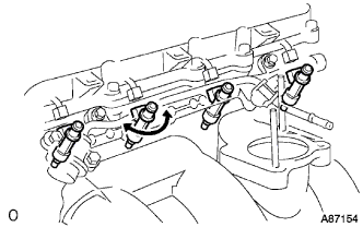
Temporarily install the 2 bolts and fuel delivery pipe together with the 4 injectors.
Note
-
Do not drop the fuel injector when installing the fuel delivery pipe.
-
Make sure that the fuel injector turns smoothly.
-
-
Fully tighten the 2 bolts.
- Torque:
- 12 N*m { 122 kgf*cm, 10 ft.*lbf }
-
Apply a light coat of grease or gasoline to the place where the delivery pipe touches the O-ring.
-
Install the 2 bolts and pressure pulsation damper assembly.
- Torque:
- 8.5 N*m { 87 kgf*cm, 75 in.*lbf }
-
Connect the 2 fuel hoses.
-
-
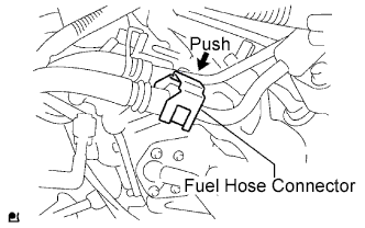
INSTALL FUEL HOSE
-
Align the connector and pipe. Push on the connector until the retainer locks with a click sound. Click here
-
Pull the connector to check that the connector is securely connected. Click here
-
Install the connector and lock it with the fuel hose connector cover. Click here
-
-
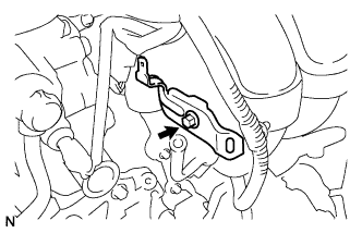
INSTALL THROTTLE BODY ASSEMBLY
-
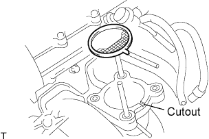
Install a new gasket onto the intake manifold.
Tech Tips
Fit the gasket to the cutout of the intake manifold.
-
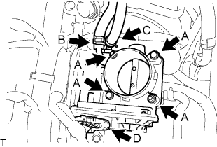
Install the throttle body assembly with the 2 bolts and 2 nuts. (A)
- Torque:
- 9.0 N*m { 92 kgf*cm, 80 in.*lbf }
-
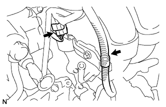
Connect the water by-pass hose. (B)
-
Connect the water by-pass hose No.2. (C)
-
Connect the throttle motor connector. (D)
-
-
INSTALL INTAKE AIR CONNECTOR
-
Temporarily install the intake air connector to the throttle body assembly.
-
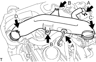
Connect the ventilation hose No.2 and the vacuum hose. (A)
-
Install the intake air connector with the 2 bolts. (B)
- Torque:
- 8.0 N*m { 82 kgf*cm, 71 in.*lbf }
-
Tighten the 2 hose clamp bolts. (C)
- Torque:
- 5.0 N*m { 51 kgf*cm, 44 in.*lbf }
-
Tighten the 2 hose clamp bolts. (D)
-
-
INSTALL ENGINE SERVICE HOLE SUB COVER SUB-ASSEMBLY
-
Install the engine service hole sub cover with the 5 bolts.
- Torque:
- 13 N*m { 133 kgf*cm, 10 ft.*lbf }
-
-
INSTALL FRONT DOOR SCUFF PLATE RH
-
INSTALL FRONT SEAT ASSEMBLY RH (for Hi-back Seat Type)
-
Perform the same procedure as above on the opposite side. Click here
-
-
INSTALL FRONT SEAT ASSEMBLY RH (for Low-back Seat Type)
-
Perform the same procedure as above on the opposite side. Click here
-
-
ADD ENGINE COOLANT
-
Firmly tighten the drain plugs and fill the reservoir tank with coolant to the top of the inlet.
-
Remove the 2-way that is located near the throttle body.
-
When air is bled and the coolant drains out, firmly install the 2-way.
-
Add coolant up to the B line mark in the reservoir tank and install the radiator cap.
Coolant Capacity Condition Capacity w/ front and rear heaters 13.6 liters (14.4 US qts, 12.0 lmp. qts) w/ front heater 11.6 liters (12.3 US qts, 10.2 lmp. qts) w/o heater 10.6 liters (11.2 US qts, 9.3 lmp. qts) -
Warm up the engine.
-
After the engine cools down, check that the coolant level is between the LOW and FULL level marks.
-
-
CONNECT CABLE TO NEGATIVE BATTERY TERMINAL
-
CHECK FOR FUEL LEAKS
-
CHECK FOR ENGINE COOLANT LEAKS
-
INSTALL ENGINE UNDER COVER NO.2 (w/ Engine Under Cover No.2)
-
Install the engine under cover No.2 together with the engine side under cover LH and engine side under cover RH (for Wide Body).
- Torque:
- 13 N*m { 133 kgf*cm, 10 ft.*lbf }
-
-
INSTALL ENGINE UNDER COVER NO.1 (w/ Engine Under Cover No.1)
- Torque:
- 13 N*m { 133 kgf*cm, 10 ft.*lbf }
-
INSPECT FUNCTION OF THROTTLE BODY
-
SYSTEM INITIALIZE